Design of insulated foundations: DESIGN OF INSULATED FOUNDATIONS
Frost-Protected Shallow Foundations – Fine Homebuilding
The footings of most foundations are placed below the frost depth. In colder areas of the United States, this can mean excavating and pouring concrete 4 ft. or more below grade. If you include enough rigid-foam insulation around a foundation, however, you can keep the soil under the house warm enough to permit shallow excavations, which can be as little as 12 in. or 16 in. deep, even in northern areas.
So-called frost-protected shallow foundations usually consist of a monolithic (thick-edged) slab wrapped with vertical and horizontal rigid-foam insulation. Although the International Residential Code (IRC) does not require a shallow foundation to have insulation below the slab, omitting the subslab insulation is not a good idea. After all, the more insulation you have under the slab, the less heat will leak out of your house into the soil below.
These shallow foundations don’t depend on leaking building heat to keep the soil warm. Instead, horizontal wings of insulation extending outward from the bottom edge of the slab help to retain the natural warmth of the earth.
Either extruded-polystyrene (XPS) or denser types of expanded-polystyrene (EPS) insulation may be used to insulate a frost-protected shallow foundation. To account for the possible performance degradation of foam insulation that remains buried for years, designers “derate” the presumed R-value of XPS from its nominal value of R-5 per in. to R-4.5 per in. The amount of insulation you’ll need depends on the air-freezing index in your area. Coincidentally, because of existing energy-code requirements, you may already be insulating your foundation walls enough to achieve the necessary R-value for a shallow foundation.
Let’s say you’re building a frost-protected shallow foundation in a Minnesota town with an air-freezing index of 2500. According to code requirements for frost-protected shallow foundations found in Table R403. 3 of the IRC, the minimum R-value of the vertical insulation at the perimeter of the slab is R-6.7 (about 1-1/2 in. of XPS). Ironically, the energy section of the IRC, which applies to all types of slabs, not just those that are frost-protected, requires more slab-edge insulation, R-10, for slabs commonly built with full-depth footings in this climate zone.
The R-value for the horizontal wing insulation in this example is R-4.9. Table R403.3 also specifies the minimum width and configuration of the wings.
Now that minimum energy-code requirements for slab insulation have overtaken the design requirements for a frost-protected shallow foundation, the line between a “conventional” slab-on-grade foundation and a frost-protected shallow foundation has been blurred. As a result, almost any monolithic slab complying with energy-code requirements can be turned into a frost-protected shallow foundation by adding the required wing insulation.
For more information, see “Revised Builder’s Guide to Frost Protected Shallow Foundations. ”
”
Code requirements spell out how much insulation must be used in a frost-protected shallow foundation. Builders of high-performance houses, however, will probably opt for much higher R-values underneath the slab. In order to meet energy efficiency requirements in Passive House buildings, for example, designers often specify much more subslab insulation than required by code. This house, in fact, had a slab insulated to R-50, five times what the IRC requires.
Pros and a few caveats
Frost-protected shallow foundations have some advantages over conventional foundations:
- They require less excavation, so smaller equipment and less labor are involved.
- Less concrete is consumed.
- Monolithic slabs are formed and poured in one shot, speeding the work schedule.
- They typically cost 15% to 21% less than a conventional foundation, according to a study by the NAHB Research Center (now the Home Innovation Research Labs).


Frost-protected shallow foundations don’t make sense everywhere, though.
- If you live where frost depths are already shallow, don’t expect any savings in labor or material, although an insulated foundation may save energy dollars later.
- Frost-protected shallow foundations aren’t appropriate for steeply sloped sites or sites with permafrost.
- In areas that are heavily infested with termites, including the southeastern United States and most of California, the use of below-grade rigid-foam insulation is not necessarily a good idea.
- Deep-rooted perennial plants shouldn’t be planted above the shallow wing insulation that surrounds the house.
- The above-grade portions of the vertical foam insulation should be protected with a durable finish material, such as Protecto Wrap, Protecto Bond, or stucco over metal or fiberglass lath.
Because most rigid insulation is either 24 in. or 48 in. wide, it makes sense to design a frost-protected shallow foundation to be 24 in. deep at the perimeter, with 16 in. below grade and 8 in. above grade.
Builder’s Tip
Monolithic-slab foundations require a perimeter trench. If vertical insulation is installed inside the formwork before the pour, the trench and the foam board can act as the lower section of the form.
Air-freezing index determines R-value
To calculate the necessary R-value of the foam needed for a frost-protected shallow foundation, most designers look up the air-freezing index for the area in which they are building. The higher the index, the colder the climate. Design guidelines for frost-protected shallow foundations can be found in an American Society of Civil Engineers publication, “Design and Construction of Frost-Protected Shallow Foundations” (ASCE 32-01). However, most residential builders will probably find it easier to follow the prescriptive requirements for these foundations in section R403.3 of the IRC, also shown here.
RELATED LINKS
- Rigid Mineral Wool Foundation Insulation Review — Fireproof, insect resistant, and able to drain water quickly, mineral wool offers extruded polystyrene some real competition.
- Insulating a Slab on Grade Foundation — Depending on your location, you may need rigid foam insulation under and around the edges of the slab.
- A Solid, Well-Insulated Foundation — A foundation made from insulating concrete forms is just the ticket for the FHB House project.
DOE Building Foundations Section 4-1
- Chapter 4
- Recommendations
Figure 4-1. Slab-on-Grade Foundation with Exterior Insulation
STRUCTURAL DESIGN
The major structural components of a slab-on-grade foundation are the floor slab itself and either grade beams or foundation walls with footings at the perimeter of the slab (see Figures 4-2 and 4-3). In some cases additional footings (often a thickened slab) are necessary under bearing walls or columns in the center of the slab. Concrete slab-on-grade floors are generally designed to have sufficient strength to support floor loads without reinforcing when poured on undisturbed or compacted soil. The proper use of welded wire fabric and concrete with a low water/cement ratio can reduce shrinkage cracking, which is an important concern for appearance and can also aid radon infiltration control strategies.
Foundation walls are typically constructed of cast-in-place concrete or concrete masonry units. Foundation walls must be designed to resist vertical loads from the structure above and transfer these loads to the footing. Concrete spread footings must provide support beneath foundation walls and columns. Similarly, grade beams at the edge of the foundation support the superstructure above. Footings must be designed with adequate size to distribute the load to the soil. Freezing water beneath footings can heave, causing cracking and other structural problems. For this reason, footings must be placed beneath the maximum frost penetration depth unless founded on bedrock or proven non-frost susceptible soil or insulated to prevent frost penetration.
Where expansive soils are present or in areas of high seismic activity, special foundation construction techniques may be necessary. In these cases, consultation with local building officials and a structural engineer is recommended.
WATER / MOISTURE MANAGEMENT
In general, moisture management schemes must control water in two states. First, since the soil in contact with the foundation and floor slab is always at 100% relative humidity, foundations must deal with water vapor that will tend to migrate toward the interior under most conditions. Second, liquid water must be kept from accumulating around and under the foundation. Liquid water comes from sources such as:
- Uncontrolled flows of surface water
- High water table
- Capillary flow through subsurface foundation assemblies
Figure 4-2. Structural System Components of Slab-on-Grade Foundation with Grade Beam
Figure 4-3. Drainage Techniques for Slab-on-Grade Foundations
Techniques for controlling the build-up and movement of moisture in the foundation are an essential component of the overall construction. Improper moisture management can lead to structural damage, damage to floor finishes, and mold growth, which can be very costly to repair and hazardous to one’s health.
The following construction practices will prevent excess water in the form of liquid water and vapor from creating problems. This is done by using adequate drainage and by the use of vapor retarders. These guidelines and recommendations apply to thickened edge/monolithic slabs and stem wall foundations with independent above grade slab configurations (PATH 2006). These two slab-on-grade configurations are illustrated in Figures 4-2 and 4-3.
- Manage exterior ground and rain water by using gutters and downspouts and by grading the ground around the perimeter at least six inches of fall over ten feet of run.
- A vapor retarder such as a 6 mil thick polyethylene sheet should be placed directly below the concrete slab (DOE 2009). The vapor retarder will prevent moisture in the ground from diffusing through the slab and into the building. It is recommended that the vapor retarder be in direct contact with the concrete slab and that no sand or gravel be placed in between (Lstiburek 2008).
- A capillary break layer consisting of three to four inches of clean gravel (no fines) should be installed below the vapor retarder. This layer helps to further prevent bulk soil moisture from wicking up to the slab and allows for that moisture to be drained out if a drainage system is installed (PATH 2006). This layer also serves as a pressure field extender for a soil gas ventilation system, if one is installed.
- Add a capillary break (a closed cell foam sill sealer or gasket) between the top of the concrete and the sill plate to prevent moisture migration between the concrete foundation and the wall structure above. For integral grade beam designs, extend the sub-slab vapor retarder under the footing, bringing it up to grade level.
- There are several different floor finishes that can be employed on a slab-on-grade foundation, however impermeable materials like vinyl flooring should be avoided because they prevent slab moisture from drying to the interior of the home. Moisture resistant finishes such as tile, terrazzo, and concrete stains are recommended specially for humid climates. Moisture sensitive finishes such as carpet and wood flooring may also be used. For these to be used appropriately, however, sub-slab, slab surface, or slab perimeter insulation should be used to moderate the slab temperature. Low temperatures can cause condensation on the slab, leading to damage to the finish as well as mold growth.
- Once the concrete for the slab has been poured, it will still contain large amounts of moisture and has to be allowed to cure. It is recommend that low water content concrete be used to reduce the amount of left over moisture that needs to dry after the slab is set. To prevent cracking and warping during the curing process, damp-curing techniques should be used in conjunction with welded wire fabric reinforcement. Horizontal, continuous, #5 rebar reinforcement at the top and bottom of stem wall or thickened slab edge should also be used to prevent cracking (PATH 2006). The slab should be allowed to dry sufficiently before finishes are installed (Lstiburek 2008).
 It is recommended that the vapor retarder be in direct contact with the concrete slab and that no sand or gravel be placed in between (Lstiburek 2008).
  Moisture resistant finishes such as tile, terrazzo, and concrete stains are recommended specially for humid climates. Moisture sensitive finishes such as carpet and wood flooring may also be used. For these to be used appropriately, however, sub-slab, slab surface, or slab perimeter insulation should be used to moderate the slab temperature. Low temperatures can cause condensation on the slab, leading to damage to the finish as well as mold growth.
  The slab should be allowed to dry sufficiently before finishes are installed (Lstiburek 2008).
 DRAINAGE AND WATERPROOFING
Since slab foundations do not enclose below-grade space, traditional waterproofing is often not required. However a continuous layer of capillary break / vapor retarder materials is required between the ground and the interior / above grade portions of the building. Depending on foundation design, this can include subslab vapor retarders, sill sealers, gaskets, waterproofing membranes, or other appropriate materials.
Rain water can be properly managed by using a well designed gutter and downspout system and by grading the ground around the foundation (6 inch drop in 10 feet) to channel water away from the foundation (Lstiburek 2006). The slab should also be elevated at least eight inches above grade to prevent water accumulating at the foundation (PATH 2006).
Since slab foundations place all the living space above grade, subgrade drainage is not always necessary. In some cases where seasonal surface water pooling may occur, or on sites with impermeable soils, it is recommended that a foundation drain be installed directly beside the bottom of the footing as recommended for basements and crawl spaces. The foundation drain assembly includes a filter fabric, gravel, and a perforated plastic drain pipe typically 4 inches in diameter. The drain runs to daylight or a sealed sump..
Figure 4-4. Potential Locations for Slab on Grade Insulation
LOCATION OF INSULATION
Insulation is included in slab-on-grade construction for two purposes:
- Insulation prevents heat loss in winter, and heat gain in summer. This effect is most pronounced at the slab perimeter, where the slab edge otherwise comes in direct contact with outdoor air.
- Even in climates and locations on the slab (perimeter vs. middle) where slab insulation may not confer large energy benefits, thermal isolation of the slab can prevent cool slab temperatures that can otherwise cause condensation inside the house. This can lead to mold and other moisture-related problems, especially if the slab is carpeted.
 This can lead to mold and other moisture-related problems, especially if the slab is carpeted.
 A wide variety of techniques can be employed to insulate slab-on-grade foundations (Figures 4-4 and 4-5). Good construction practice demands elevating the slab above grade by no less than 8 inches to isolate the wood framing from rain splash, soil dampness, and termites, and to keep the subslab drainage layer above the surrounding ground. The most intense heat transfer is through this small area of foundation wall above grade, so it requires special care in detailing and installation. Heat is also transferred between the slab and the soil, through which it migrates to the exterior ground surface and the air. Heat transfer with the soil is greatest at the edge, and diminishes rapidly with distance from it. In hot climates, direct coupling of the soil to the slab may moderate cooling loads, though at the risk of condensing moisture from the indoor air.
Both components of the slab heat transfer — at the edge and through the soil — must be considered in designing the insulation system. Insulation can be placed vertically outside the foundation wall or grade beam. This approach effectively insulates the exposed slab edge above grade and extends down to reduce heat flow from the floor slab to the ground surface outside the building. Vertical exterior insulation (Figure 4-5a) is the only method of reducing heat loss at the edge of an integral grade beam and slab foundation. For stemwall foundations, the major advantage of exterior insulation is that the interior joint between the slab and foundation may not need to be insulated, which simplifies construction. One drawback is that rigid insulation must be covered above grade with a protective board, coating, or flashing material. Another limitation is that the depth of the exterior insulation is controlled by the footing depth. However additional exterior insulation can be provided by extending insulation horizontally from the foundation wall. Since this approach can control frost penetration near the footing, it can be used to reduce footing depth requirements under certain circumstances (Figure 4-5a).
 This method is known as a “frost protected shallow foundation” (FPSF). A variation for unheated buildings is shown in Figure 4-5b. See NAHB (2004) for more information on this technique, which can substantially reduce the initial foundation construction cost.
Exterior insulation must be approved for below-grade use. Typically, three products are used below grade: extruded polystyrene, expanded polystyrene, and rigid mineral fiber panels. (Baechler et al. 2005). Extruded polystyrene (nominal R-5 per inch) is a common choice. Expanded polystyrene (nominal R-4 per inch) is less expensive, but it has a lower insulating value. Below-grade foams can be at risk for moisture accumulation under certain conditions. Experimental data indicate that this moisture accumulation may reduce the effective R-value as much as 35%-44%. Research conducted at Oak Ridge National Laboratories studied the moisture content and thermal resistance of foam insulation exposed below grade for fifteen years; moisture may continue to accumulate and degrade thermal performance beyond the fifteen-year timeframe of the study. This potential reduction should be accounted for when selecting the amount and type of insulation to be used (Kehrer, et al., 2012, Crandell 2010).
Figure 4-5. Potential Locations for Slab on Grade Insulation
Insulation also can be placed vertically on the interior of a stemwall or horizontally under the slab. In both cases, heat loss from the floor is reduced and the difficulty of placing and protecting exterior insulation is avoided. Interior vertical insulation is limited to the depth of the footing but underslab insulation is not limited in this respect. Usually the outer 2 to 4 feet of the slab perimeter is insulated but the entire floor may be insulated if desired. Remember that condensation control is an important consideration, along with heating energy use. It is essential to insulate the joint between the slab and the foundation wall whenever insulation is placed inside the foundation wall or under the slab. Otherwise, a significant amount of heat transfer occurs through the thermal bridge at the slab edge. The insulation is generally limited to no more than 1 inch in thickness at this point. Figure 4-4d shows insulation under the slab and at the slab edge to control the temperature of the slab, with exterior insulation placed vertically and horizontally to prevent frost penetration to the footing.
Another option for insulating a slab-on-grade foundation is to place insulation above the floor slab (Figure 4-5c). This may be the only option for retrofit applications. It can be appropriate for new construction as well, especially when wood is the desired floor finish. These techniques have critical details that must be followed to avoid moisture problems; full descriptions can be found in Lstiburek (2006).
Other specialty systems can be used for slab-on-grade stemwalls. These include insulated concrete forms (ICFs), post-tensioned slabs, and systems that place foam insulation between two layers of cast in place concrete.
Figure 4-6. Slab-on-Grade Termite Control Techniques
TERMITE AND WOOD DECAY CONTROL TECHNIQUES
Techniques for controlling the entry of termites through residential foundations are necessary in much of the United States (see Figure 4-6). Consult with local building officials and codes for further details.
- Minimize soil moisture around the foundation by surface drainage and by using gutters, downspouts, and runouts to remove roof water.
- Remove all roots, stumps, and wood from the site. Wood stakes and form work should also be removed from the foundation area.
- Treat soil with termiticide on all sites vulnerable to termites (Labs et al. 1988).
- Place a bond beam or course of solid cap blocks on top of all concrete masonry foundation walls to ensure that no open cores are left exposed. Alternatively, fill all cores on the top course with mortar. The mortar joint beneath the top course or bond beam should be reinforced for additional insurance.
- Place the sill plate at least 8 inches above grade; it should be pressure-preservative treated to resist decay. Since termite shields are often damaged or not installed carefully enough, they are considered optional and should not be regarded as sufficient defense by themselves.
- Be sure that exterior wood siding and trim are at least 6 inches above grade.
- Construct porches and exterior slabs so that they slope away from the foundation wall, are reinforced with steel or wire mesh, usually are at least 2 inches below exterior siding, and are separated from all wood members by a 2-inch gap visible for inspection or a continuous metal flashing soldered at all seams.
- Fill the joint between a slab-on-grade floor and foundation wall with liquid-poured urethane caulk or coal tar pitch to form a termite and radon barrier.

Plastic foam and mineral wool insulation materials have no food value to termites, but they can provide protective cover and easy tunneling. Insulation installations can be detailed for ease of inspection, although often by sacrificing thermal efficiency.
In principle, termite shields offer protection, but should not be relied upon as a barrier. Termite shields are shown in this document as a component of all slab-on-grade designs. Their purpose is to force any insects ascending through the wall out to the exterior, where they can be seen. For this reason, termite shields must be continuous, and all seams must be sealed to prevent bypass by the insects.
These concerns over insulation and the unreliability of termite shields have led to the conclusion that soil treatment is the most effective technique to control termites with an insulated foundation. However, the restrictions on widely used termiticides may make this option either unavailable or cause the substitution of products that are more expensive and possibly less effective. This situation should encourage insulation techniques that enhance visual inspection and provide effective barriers to termites. For more information on termite mitigation techniques, see NAHB (2006).
Figure 4-7. Slab-on-Grade Radon Control Techniques
RADON CONTROL TECHNIQUES
Sealing the Slab
The following techniques for minimizing radon infiltration through a slab-on-grade foundation are appropriate, especially in moderate or high potential radon areas (zones 1 and 2) as designated by EPA (see Figures 4-7 and 4-8). To determine this, contact the state radon staff.
- Use solid pipes for floor discharge drains to daylight or provide mechanical traps if they discharge to subsurface drains.
- Lay a 6-mil polyethylene film on top of the gravel drainage layer beneath the slab. This film serves both as a radon and moisture retarder. Slit an “x” in the polyethylene membrane at penetrations. Turn up the tabs and seal them to the penetration using caulk or tape. Care should be taken to avoid unintentionally puncturing the barrier; consider using riverbed gravel if available at a reasonable price. The round riverbed gravel allows for freer movement of the soil gas and has no sharp edges to penetrate the polyethylene. The edges should be lapped at least 12 inches. The polyethylene should extend over the top of the foundation wall, or extend under a monolithic slab-grade beam or patio, terminating no lower than finished grade. Use concrete with a low water/cement ratio to minimize cracking.
- Provide an isolation joint between the foundation wall and slab floor where vertical movement is expected. After the slab has cured for several days, seal the joint by pouring polyurethane or similar caulk into the 1/2-inch channel formed with a removable strip. Polyurethane caulks adhere well to masonry and are long-lived. They do not stick to polyethylene. Do not use latex caulk.
- Install welded wire in the slab to reduce the impact of shrinkage cracking. Consider control joints or additional reinforcing near the inside corner of “L” shaped slabs. Two pieces of No. 4 reinforcing bar, 3 feet long and on 12-inch centers, across areas where additional stress is anticipated, should reduce cracking. Use of fibers within concrete will also reduce the amount of plastic shrinkage cracking.
- Control joints should be finished with a 1/2-inch depression. Fill this recess fully with polyurethane or similar caulk.
- Minimize the number of pours to avoid cold joints. Begin curing the concrete immediately after the pour, according to recommendations of the American Concrete Institute (1980; 1983). At least three days are required at 70F, and longer at lower temperatures. Use an impervious cover sheet or wetted burlap.
- Form a gap of at least 1/2-inch width around all plumbing and utility lead-ins through the slab to a depth of at least 1/2 inch. Fill with polyurethane or similar caulking.
- Place HVAC condensate drains so that they run to daylight outside the building envelope, or to a floor drain suitably sealed against radon penetration. Condensate drains that connect to dry wells or other soil may become direct conduits for soil gas, and can be a major entry point for radon.
- Place a solid block course, bond beam, or cap block on top of all masonry foundation walls to seal cores, or fill open block cores in the top course with concrete. An alternative approach is to leave the masonry cores open and fill solid at the time the floor slab is cast by flowing concrete into the top course of block.
- Do not place HVAC ducts under the slab.

 Begin curing the concrete immediately after the pour, according to recommendations of the American Concrete Institute (1980; 1983). At least three days are required at 70F, and longer at lower temperatures. Use an impervious cover sheet or wetted burlap.
Figure 4-8. Soil Gas Collection and Discharge Techniques
Intercepting Soil Gas
The most effective way to limit radon and other soil gas entry is through the use of active soil depressurization (ASD). ASD works by lowering the air pressure in the soil relative to the indoors. Avoiding foundation openings to the soil, or sealing those openings, as well as limiting sources of indoor depressurization aid ASD systems. Sometimes a passive soil depressurization (PSD, with no fan) system is used. If post-occupancy radon testing indicates further radon reduction is desirable, a fan can be installed in the vent pipe (see Figure 4-8).
Subslab depressurization has proven to be an effective technique for reducing radon concentrations to acceptable levels, even in homes with extremely high concentrations (Dudney 1988). This technique lowers the pressure around the foundation envelope, causing the soil gas to be routed into a collection system, avoiding the inside spaces and discharging to the outdoors.
A foundation with good subsurface drainage already has a collection system. The underslab gravel drainage layer can be used to collect soil gas. It should be at least 4 inches thick, and of clean aggregate no less than 1/2 inch in diameter. The gravel should be covered with a 6-mil polyethylene radon and vapor retarder.
A 3- or 4-inch diameter PVC vent pipe should be routed from the subslab gravel layer through the conditioned portion of the building and through the highest roof plane. The pipe should terminate below the slab with a “tee” fitting. To prevent clogging the pipe with gravel, ten-foot lengths of perforated draintile can be attached to the legs of the tee, and sealed at the ends. Alternately, the vent pipe can be connected to a perimeter drain system, as long as that system does not connect to the outdoor environment. Horizontal vent pipes could connect the vent stack through below grade walls to permeable areas beneath adjoining slabs. A single vent pipe is adequate for most houses with less than 2,500 square feet of slab area that also include a permeable subslab layer. The vent pipe is routed to the roof through plumbing chases, interior walls, or closets.
A PSD system requires the floor slab to be nearly airtight so that collection efforts are not short-circuited by drawing excessive room air down through the slab and into the system. Cracks, slab penetrations, and control joints must be sealed. Floor drains that discharge to the gravel beneath the slab should be avoided, but when used, should be fitted with a mechanical trap capable of providing an airtight seal.
While a properly installed passive soil depressurization (PSD) system may reduce indoor radon concentrations by about 50%, active soil depressurization (ASD) systems can reduce indoor radon concentrations by up to 99%. A PSD system is more limited in terms of vent pipe routing options, and is less forgiving of construction defects than ASD systems. Furthermore, in new construction, small ASD fans (25-40 watt) may be used with minimal energy impact. Active systems use quiet, in-line duct fans to draw gas from the soil. The fan should be located outside, and ideally above, the conditioned space so that any air leaks from the positive pressure side of the fan or vent stack are not in the living space. The fan should be oriented to prevent accumulation of condensed water in the fan housing. The ASD stack should be routed up through the building or an attached garage or carport, and extend twelve inches above the roof. It can also be carried out through the band joist and up along the outside of wall, to a point high enough so that there is no danger of the exhaust being redirected into the building through attic vents or other pathways. Because PSD systems rely on natural buoyancy to operate, a PSD stack must be routed through the conditioned portion of the home.
A fan capable of maintaining 0.2 inch of water suction under installation conditions is adequate for serving subslab collection systems for most houses (Labs 1988). This is often achieved with a 0.03 hp (25W), 160 cfm centrifugal fan (maximum capacity) capable of drawing up to 1 inch of water before stalling. Under field conditions of 0.2 inch of water, such a fan operates at about 80 cfm.
It is possible to test the suction of the subslab system by drilling a small (1/4-inch) hole in areas of the slab remote from the suction point, and measuring the suction through the hole using a micromanometer or inclined manometer. The goal of a subslab depressurization system is to create negative air pressure below the slab, relative to the air pressure in the adjacent interior space. A suction of 5 Pascals is considered satisfactory when the house is placed in a worst-case depressurization condition (i.e., house closed, all exhaust fans and devices operating, and with the HVAC system operating with interior doors shut). The hole must be sealed after the test.
PSD systems require near perfection in sealing of openings to the soil, since the system relies on a 3- or 4-inch pipe to vent more effectively than the entire house. Sealing openings to the soil is less critical for radon control with ASD systems, although it is highly desirable in order to limit the energy penalty associated with conditioned indoor air leaking into a depressurized subslab, and from there to the outdoors. ASD fans have service lives averaging about ten years, with a higher life expectancy if the fan is protected from the elements. Since an ASD system may be turned off by occupants, service switches are usually located in areas with limited access.
For more information visit the Building America Solution Center.
Frost-Protected Shallow Foundation Footings – Concrete Network
What are Frost-Protected Shallow Footings and Why Are They Used?
Most building codes in cold-climates require foundation footings be placed below the frost line, which can be about 4-feet deep in the northern United States. The goal is to protect foundations from frost heaving.
There is an exception to this standard: many codes permit foundations to lie above the frost line as long as they’re “protected from frost.” However, approval depends on local code officials, and may require special engineering. The 1995 edition of the Council of American Building Officials (CABO) One and Two-Family Dwelling Code includes simplified guidelines for building slab-on-grade homes with shallow foundations that are protected from frost by rigid foam insulation.
A frost protected shallow foundation (FPSF) is a practical alternative to deeper, more-costly foundations in cold regions with seasonal ground freezing and the potential for frost heave.
Find slab and foundation contractors near me
Figure 1 shows an FPSF and a conventional foundation. An FPSF incorporates strategically placed insulation to raise the frost depth around a building, thereby allowing foundation depths as shallow as 16 inches, even in the most severe climates. The most extensive use has been in the Nordic countries, where over one million FPSF homes have been constructed successfully over the last 40 years. The FPSF is considered standard practice for residential buildings in Scandinavia.
FPSF Resources
History of frost-protected shallow foundations
HUD FPSF Study Findings
Advantages of FPSF
Building Codes and FPSF
Frost Action and Foundations (the nitty gritty on how frost heave works)
Types of Insulation Allowed for FPSF
Types of FPSF
Applications and Limitations of FPSF
FPSF in Heated Buildings
FPSF in Unheated Buildings
Recommended Construction Methods and Details
Simplified Design Method
Detailed Method for Heated Buildings
How FPSF Works
The frost protected shallow foundation technology recognizes the thermal interaction of building foundations with the ground. Heat input to the ground from buildings effectively raises the frost depth at the perimeter of the foundation. This effect and other conditions that regulate frost penetration into the ground are illustrated in Figure 2.
It is important to note that the frost line rises near a foundation if the building is heated. This effect is magnified when insulation is strategically placed around the foundation. The FPSF also works on an unheated building by conserving geothermal heat below the building. Unheated areas of homes such as garages may be constructed in this manner.
Figure 3 illustrates the heat exchange process in an FPSF, which results in a higher frost depth around the building. The insulation around the foundation perimeter conserves and redirects heat loss through the slab toward the soil below the foundation. Geothermal heat from the underlying ground also helps to raise the frost depth around the building.
FPSFs are most suitable for slab-on-grade homes on sites with moderate to low sloping grades. The method may, however, be used effectively with walk-out basements by insulating the foundation on the downhill side of the house, thus eliminating the need for a stepped footing. FPSFs are also useful for remodeling projects in part because they minimize site disturbance. In addition to residential, commercial, and agricultural buildings, the technology has been applied to highways, dams, underground utilities, railroads, and earth embankments.
More Common Questions and Answers
Question No. 1: How does insulation stop frost heave from occurring?
Frost heave can only occur when all of the following three conditions are present: 1) the soil is frost susceptible (large silt fraction), 2) sufficient moisture is available (soil is above approximately 80 percent saturation), and 3) sub-freezing temperatures are penetrating the soil. Removing one of these factors will negate the possibility of frost damage. Insulation as required in this design guide will prevent underlying soil from freezing (an inch of polystyrene insulation, R4. 5, has an equivalent R-Value of about 4 feet of soil on average). The use of insulation is particularly effective on a building foundation for several reasons. First, heat loss is minimized while storing and directing heat into the foundation soil — not out through the vertical face of the foundation wall. Second, horizontal insulation projecting outward will shed moisture away from the foundation further minimizing the risk of frost damage. Finally, because of the insulation, the frost line will rise as it approaches the foundation. Since frost heave forces act perpendicular to the frost line, heave forces, if present, will act in a horizontal direction and not upwards.
Question No. 2: Does the soil type or ground cover (e.g., snow) affect the amount of insulation required?
By design, the proposed insulation requirements are based on the worst-case ground condition of no snow or organic cover on the soil. Likewise, the recommended insulation will effectively prevent freezing of all frost-susceptible soils. Because of the heat absorbed (latent heat) during the freezing of water (phase change), increased amounts of soil water will tend to moderate the frost penetration or temperature change of the soil-water mass. Since soil water increases the heat capacity of the soil, it further increases the resistance to freezing by increasing the soil’s “thermal mass” and adding a significant latent heat effect. Therefore, the proposed insulation requirements are based on a worst-case, silty soil condition with sufficient moisture to allow frost heave but not so much as to cause the soil itself to drastically resist the penetration of the frost line. Actually, a coarse grained soil (non-frost susceptible) which is low in moisture will freeze faster and deeper, but with no potential for frost damage. Thus, the proposed insulation recommendations effectively mitigate frost heave for all soil types under varying moisture and surface conditions.
Question No. 3: How long will the insulation protect the foundation?
This question is very important when protecting homes or other structures which have a long life expectancy. The ability of insulation to perform in below-ground conditions is dependent on the product type, grade, and moisture resistance. In Europe, polystyrene insulation has been used to protect foundations for nearly 40 years with no experience of frost heave. Thus, with proper adjustment of R-values for below-ground service conditions, both extruded polystyrene (XPS) and expanded polystyrene (EPS) can be used with assurance of performance. In the United States, XPS has been studied for Alaskan highway and pipeline projects, and it has been found that after 20 years of service and at least 5 yrs of submergence in water that the XPS maintained its R-value (ref. McFadden and Bennett, Construction in Cold Regions: A Guide for Planners, Engineers, Contractors, and Managers , J. Wiley & Sons, Inc., 1991. pp328-329). For reasons of quality assurance, both XPS and EPS can be readily identified by labelling corresponding to current ASTM standards.
Question No. 4: What happens if the heating system fails for a time during the winter?
For all types of construction, heat loss through the floor of a building contributes to geothermal heat storage under the building, which during the winter is released at the foundation perimeter. Using insulated footings will effectively regulate the stored heat loss and retard penetration of the frost line during a period of heating system failure or set-back. Conventional foundations, with typically less insulation, do not offer this level of protection and the frost may penetrate more quickly through the foundation wall and into interior areas below the floor slab. With ad-freezing (the frozen bond between the water in the soil and the foundation wall), frost does not need to penetrate below footings to be dangerous to light construction. In this sense, frost protected footings are more effective in preventing frost damage. The proposed insulation requirements are based on highly accurate climate information verified by up to 86 years of winter freezing records for over 3,000 weather stations across the United States. The insulation is sized to prevent foundation soil freezing for a 100-year return period winter freezing event with a particularly rigorous condition of no snow or ground cover.
 Even then, it is highly unlikely that during such an event their will be no snow cover, sufficiently high ground moisture, and an extended loss of building heat.
Question No. 5: Why are greater amounts of insulation needed at the corners of the foundation?
Heat loss occurs outward from the foundation walls and is, therefore, intensified at the proximity of an outside corner because of the combined heat loss from two adjacent wall surfaces. Consequently, to protect foundation corners from frost damage, greater amounts of insulation are required in the corner regions. Thus, an insulated footing design will provide additional protection at corners where the risk of frost damage is higher.
Question No. 6: What experience has the U.S. seen with this technology?
Frost protected insulated footings were used as early as the 1930s by Frank Lloyd Wright in the Chicago area. But since that time, the Europeans have taken the lead in applying this concept over the last 40 years. There are now over 1 million homes in Norway, Sweden, and Finland with insulated shallow footings which are recognized in the building codes as a standard practice. In the United States, insulation has been used to prevent frost heave in many special engineering projects (i.e., highways, dams, pipelines, and engineered buildings). Its use on home foundations has been accepted by local codes in Alaska, and it has seen scattered use in uncoded areas of other states. It is likely that there are several thousand homes with variations of frost protected insulated footings in the United States (including Alaska).
To verify the technology in the United States, five test homes were constructed in Vermont, Iowa, North Dakota, and Alaska. The homes were instrumented with automated data acquisition systems to monitor ground, foundation, slab, indoor, and outdoor temperatures at various locations around the foundations. The performance observed was in agreement with the European experience in that the insulated footings prevented the foundation soil from freezing and heaving even under rigorous climatic and soil conditions (ref. U.S. Department of Housing and Urban Development, “Frost Protected Shallow Foundations for Residential Construction”, Washington, DC, 1993).
Question No. 7: How energy efficient and comfortable are slab foundations with frost protected footings?
The insulation requirements for frost protected footings are minimum requirements to prevent frost damage. The requirements will provide a satisfactory level of energy efficiency, comfort, and protection against moisture condensation. Since these requirements are minimums, additional insulation may be applied to meet special comfort objectives or more stringent energy codes.
FPSF Construction Issues
These issues apply to the construction of any FPSF:
Cold bridges. Cold bridges are created when building materials with high thermal conductivity, such as concrete, are directly exposed to outside temperatures. Foundation insulation should be placed such that continuity is maintained with the insulation of the house envelope. Cold bridges may increase the potential for frost heave, or at the least, create localized lower temperatures or condensation on the slab surface. Care must be taken during construction to ensure proper installation of the insulation.
Drainage. Good drainage is important with any foundation and FPSF is no exception. Insulation performs better in drier soil conditions. Ensure that ground insulation is adequately protected from excessive moisture through sound drainage practices, such as sloping the grade away from the building.
Insulation should always be placed above the level of the ground water table. A layer of gravel, sand, or similar material is recommended for improved drainage as well as to provide a smooth surface for placement of any horizontal wing insulation. A minimum 6-inch drain layer is required for unheated FPSF designs. Beyond the 12-inch minimum foundation depth required by building codes, the additional foundation depth required by an FPSF design may be made up of compacted, non-frost susceptible fill material such as gravel, sand, or crushed rock.
Slab surface temperatures (moisture, comfort, and energy efficiency). The minimum insulation levels prescribed in this design procedure protect the foundation soil from frost. They also provide satisfactory slab surface temperatures to prevent moisture condensation and satisfy a minimum degree of thermal comfort. Since the design procedure provides minimum insulation requirements, the foundation insulation may be increased to meet special needs concerning these issues and energy efficiency. Successfully limiting cold bridging is critical — use of the stem wall and slab technique, in effect, adds a second thermal break between the slab and stem wall. Increasing the vertical wall insulation thickness above the minimum requirements for frost protection will also improve energy efficiency and thermal comfort. Selection of a finish floor material such as carpeting decreases the surface contact between occupant and the slab, giving a warmer feel.
Heated slabs and energy efficiency. FPSF design procedure can be applied to all slab-on-grade techniques, including those with in-slab heat which provide excellent thermal comfort. If an in-slab heating system is used, additional insulation below the slab and around the perimeter is recommended for improved energy efficiency.
Protecting the insulation.Because the vertical wall insulation around a foundation extends above grade and is subject to ultraviolet radiation and physical abuse, that portion must be protected with a coating or covering that is both tough and durable. Some methods to consider are a stucco finish system or similar brush-on coatings, pre-coated insulation products, flashings, and pressure treated plywood. The builder should always verify that such materials are compatible with the insulation board. The protective finish should be applied before backfilling, since it must extend at least four inches below grade. Also, polystyrene insulation is easily broken down by hydrocarbon solvents such as gasoline, benzene, diesel fuel, and tar. Care should be taken to prevent insulation damage during handling, storage, and backfilling. Also, where termites are a concern, standard preventative practice such as soil treatment, termite shields, etc. is suggested.
Insulation specifications.Because some insulation materials resist water absorption less effectively than others, which in turn degrades their thermal resistance (R-values), insulation material should be specified carefully. The following effective R-values shall be used to determine insulation thicknesses required for this application: Type II expanded polystyrene – 2.4 R per inch; Types IV, V, VI, VII extruded polystyrene – 4.5 R per inch; Type IX expanded polystyrene – 3.2 R per inch. Special applications, such as bearing structural loads from footings, may require higher density polystyrenes for the required compressive strengths. The builder is referred to manufacturers for product-specific information.
Doorways and Thresholds. At doorways where the threshold overhangs the vertical wall insulation, the insulation should be cut out as required to provide solid blocking for adequate bearing and fastening of the threshold. The size of the cut-outs should be minimized.
Landscaping and wing insulation. In situations where wide horizontal wing insulation is required (e.g., greater than 3 to 4 foot widths), this may deter the location of large plantings close to the home. In some of these cases, using thicker wing insulation or increasing the foundation depth will decrease the required width of the wing insulation.
Foundation height. Given that most polystyrene insulation boards are typically available in 24 inch and 48 inch widths, 24 inches becomes a practical height for many foundations. This provides 16 inches of the foundation below grade and 8 inches above grade.
Excavation. Generally, lightweight equipment is adequate for FPSFs because little excavation is required. As with any foundation, organic soil layers (top soil) should be removed to allow the foundation to bear on firm soil or compacted fills.
Construction scheduling. The foundation should be completed and the building enclosed and heated prior to the freezing weather, similar to conventional construction practice.
| STATE | AIR-FREEZING INDEX | |||||
| 1,500 or less | 2,000 | 2,500 | 3,000 | 3,500 | 4,000 | |
| Alabama | All counties | — | — | — | — | — |
| Alaska | Ketchikan Gateway, Prince of Wales-Outer Ketchikan (CA), Sitka, Wrangell-Petersburg (CA) | — | Aleutians West (CA), Haines, Juneau, Skagway-Hoonah-Angoon (CA), Yakutat | — | — | All counties not listed |
| Arizona | All counties | — | — | — | — | — |
| Arkansas | All counties | — | — | — | — | — |
| California | All counties not listed | Nevada, Sierra | — | — | — | — |
| Colorado | All counties not listed | Archuleta, Custer, Fremont, Huerfano, Las Animas, Ouray, Pitkin, San Miguel | Clear Creek, Conejos, Costilla, Dolores, Eagle, La Plata, Park, Routt, San Juan, Summit | Alamosa, Grand, Jackson, Larimer, Moffat, Rio Blanco, Rio Grande | Chaffee, Gunnison, Lake, Saguache | Hinsdale, Mineral |
| Connecticut | All counties not listed | Hartford, Litchfield | — | — | — | — |
| Delaware | All counties | — | — | — | — | — |
| District of Columbia | All counties | — | — | — | — | — |
| Florida | All counties | — | — | — | — | — |
| Georgia | All counties | — | — | — | — | — |
| Hawaii | All counties | — | — | — | — | — |
| Idaho | All counties not listed | Adams, Bannock, Blaine, Clearwater, Idaho, Lincoln, Oneida, Power, Valley, Washington | Bingham, Bonneville, Camas, Caribou, Elmore, Franklin, Jefferson, Madison, Teton | Bear Lake, Butte, Custer, Fremont, Lemhi | Clark | — |
| Illinois | All counties not listed | Boone, Bureau, Cook, Dekalb, DuPage, Fulton, Grundy, Henderson, Henry, Iroquois, Jo Daviess, Kane, Kankakee, Kendall, Knox, La Salle, Lake, Lee, Livingston, Marshall, Mason, McHenry, McLean, Mercer, Peoria, Putnam, Rock Island, Stark, Tazewell, Warren, Whiteside, Will, Woodford | Carroll, Ogle, Stephenson, Winnebago | — | — | — |
| Indiana | All counties not listed | Allen, Benton, Cass, Fountain, Fulton, Howard, Jasper, Kosciusko, La Porte, Lake, Marshall, Miami, Newton, Porter, Pulaski, Starke, Steuben, Tippecanoe, Tipton, Wabash, Warren, White | — | — | — | — |
| Iowa | Appanoose, Davis, Fremont, Lee, Van Buren | All counties not listed | Allamakee, Black Hawk, Boone, Bremer, Buchanan, Buena Vista, Butler, Calhoun, Cerro Gordo, Cherokee, Chickasaw, Clay, Clayton, Delaware, Dubuque, Fayette, Floyd, Franklin, Grundy, Hamilton, Hancock, Hardin, Humboldt, Ida, Jackson, Jasper, Jones, Linn, Marshall, Palo Alto, Plymouth, Pocahontas, Poweshiek, Sac, Sioux, Story, Tama, Webster, Winnebago, Woodbury, Worth, Wright | Dickinson, Emmet, Howard, Kossuth, Lyon, Mitchell, O’Brien, Osceola, Winneshiek | — | — |
| Kansas | All counties | — | — | — | — | — |
| Kentucky | All counties | — | — | — | — | — |
| Louisiana | All counties | — | — | — | — | — |
| Maine | York | Knox, Lincoln, Sagadahoc | Androscoggin, Cumberland, Hancock, Kennebec, Waldo, Washington | Aroostook, Franklin, Oxford, Penobscot, Piscataquis, Somerset | — | — |
| Maryland | All counties | — | — | — | — | — |
| Massachusetts | All counties not listed | Berkshire, Franklin, Hampden, Worcester | — | — | — | — |
| Michigan | Berrien, Branch, Cass, Kalamazoo, Macomb, Ottawa, St. Clair, St. Joseph Clair, St. Joseph |
All counties not listed | Alger, Charlevoix, Cheboygan, Chippewa, Crawford, Delta, Emmet, Iosco, Kalkaska, Lake, Luce, Mackinac, Menominee, Missaukee, Montmorency, Ogemaw, Osceola, Otsego, Roscommon, Schoolcraft, Wexford | Baraga, Dickinson, Iron, Keweenaw, Marquette | Gogebic, Houghton, Ontonagon | — |
| Minnesota | — | — | Houston, Winona | All counties not listed | Aitkin, Big Stone, Carlton, Crow Wing, Douglas, Itasca, Kanabec, Lake, Morrison, Pine, Pope, Stearns, Stevens, Swift, Todd, Wadena | Becker, Beltrami, Cass, Clay, Clearwater, Grant, Hubbard, Kittson, Koochiching, Lake of the Woods, Mahnomen, Marshall, Norman, Otter Tail, Pennington, Polk, Red Lake, Roseau, St. Louis, Traverse, Wilkin Louis, Traverse, Wilkin |
| Mississippi | All counties | — | — | — | — | — |
| Missouri | All counties not listed | Atchison, Mercer, Nodaway, Putnam | — | — | — | — |
| Montana | Mineral | Broadwater, Golden Valley, Granite, Lake, Lincoln, Missoula, Ravalli, Sanders, Sweet Grass | Big Horn, Carbon, Jefferson, Judith Basin, Lewis and Clark, Meagher, Musselshell, Powder River, Powell, Silver Bow, Stillwater, Westland | Carter, Cascade, Deer Lodge, Falcon, Fergus, Flathead, Gallatin, Glacier, Madison, Park, Petroleum, Ponder, Rosebud, Teton, Treasure, Yellowstone | Beaverhead, Blaine, Chouteau, Custer, Dawson, Garfield, Liberty, McCone, Prairie, Toole, Wibaux | Daniels, Hill, Phillips, Richland, Roosevelt, Sheridan, Valley |
| Nebraska | Adams, Banner, Chase, Cheyenne, Clay, Deuel, Dundy, Fillmore, Franklin, Frontier, Furnas, Gage, Garden, Gosper, Harlan, Hayes, Hitchcock, Jefferson, Kimball, Morrill, Nemaha, Nuckolls, Pawnee, Perkins, Phelps, Red Willow, Richardson, Saline, Scotts Bluff, Seward, Thayer, Webster | All counties not listed | Boyd, Burt, Cedar, Cuming, Dakota, Dixon, Dodge, Knox, Thurston | — | — | — |
| Nevada | All counties not listed | Elko, Eureka, Nye, Washoe, White Pine | — | — | — | — |
| New Hampshire | — | All counties not listed | — | — | — | Carroll, Coos, Grafton |
| New Jersey | All counties | — | — | — | — | — |
| New Mexico | All counties not listed | Rio Arriba | Colfax, Mora, Taos | — | — | — |
| New York | Albany, Bronx, Cayuga, Columbia, Cortland, Dutchess, Genessee, Kings, Livingston, Monroe, Nassau, New York, Niagara, Onondaga, Ontario, Orange, Orleans, Putnam, Queens, Richmond, Rockland, Seneca, Suffolk, Wayne, Westchester, Yates | All counties not listed | Clinton, Essex, Franklin, Hamilton, Herkimer, Jefferson, Lewis, St. Lawrence, Warren Lawrence, Warren |
— | — | — |
| North Carolina | All counties | — | — | — | — | — |
| North Dakota | — | — | — | Billings, Bowman | Adams, Dickey, Golden Valley, Hettinger, LaMoure, Oliver, Ransom, Sargent, Sioux, Slope, Stark | All counties not listed |
| Ohio | All counties not listed | Ashland, Crawford, Defiance, Holmes, Huron, Knox, Licking, Morrow, Paulding, Putnam, Richland, Seneca, Williams | — | — | — | — |
| Oklahoma | All counties | — | — | — | — | — |
| Oregon | All counties not listed | Baker, Crook, Grant, Harney | — | — | — | — |
| Pennsylvania | All counties not listed | Berks, Blair, Bradford, Cambria, Cameron, Centre, Clarion, Clearfield, Clinton, Crawford, Elk, Forest, Huntingdon, Indiana, Jefferson, Lackawanna, Lycoming, McKean, Pike, Potter, Susquehanna, Tioga, Venango, Warren, Wayne, Wyoming | — | — | — | — |
| Rhode Island | All counties | — | — | — | — | — |
| South Carolina | All counties | — | — | — | — | — |
| South Dakota | — | Bennett, Custer, Fall River, Lawrence, Mellette, Shannon, Todd, Tripp | Bon Homme, Charles Mix, Davison, Douglas, Gregory, Jackson, Jones, Lyman | All counties not listed | Beadle, Brookings, Brown, Campbell, Codington, Corson, Day, Deuel, Edmunds, Faulk, Grant, Hamlin, Kingsbury, Marshall, McPherson, Perkins, Roberts, Spink, Walworth | — |
| Tennessee | All counties | — | — | — | — | — |
| Texas | All counties | — | — | — | — | — |
| Utah | All counties not listed | Box Elder, Morgan, Weber | Garfield, Salt Lake, Summit | Carbon, Daggett, Duchesne, Rich, Sanpete, Uintah, Wasatch | — | — |
| Vermont | — | Bennington, Grand Isle, Rutland, Windham | Addison, Chittenden, Franklin, Orange, Washington, Windsor | Caledonia, Essex, Lamoille, Orleans | — | — |
| Virginia | All counties | — | — | — | — | — |
| Washington | All counties not listed | Chelan, Douglas, Ferry, Okanogan | — | — | — | — |
| West Virginia | All counties | — | — | — | — | — |
| Wisconsin | — | Kenosha, Kewaunee, Racine, Sheboygan, Walworth | All counties not listed | Ashland, Barron, Burnett, Chippewa, Clark, Dunn, Eau Claire, Florence, Forest, Iron, Jackson, La Crosse, Langlade, Marathon, Monroe, Pepin, Polk, Portage, Price, Rust, St. Croix, Taylor, Trempealeau, Vilas, Wood Croix, Taylor, Trempealeau, Vilas, Wood |
Bayfield, Douglas, Lincoln, Oneida, Sawyer, Washburn | — |
| Wyoming | Goshen, Platte | Converse, Crook, Laramie, Niobrara | Campbell, Carbon, Hot Springs, Johnson, Natrona, Sheridan, Uinta, Weston | Albany, Big Horn, Park, Washakie | Fremont, Teton | Lincoln, Sublette, Sweetwater |
Slab-on-Grade Foundation Detail & Insulation, Building Guide
Ecohome
Updated: July 28, 2021
Emmanuel Cosgrove
Slab on Grade foundation, detail design; the basics
There are many different soil conditions and corresponding slab designs. This page is about how to build a thickened edge concrete slab on grade FPSF footing on soil with a high water table to prevent frost heave, by first installing drainage below the slab.
Related slab on grade foundation pages:
- Slab-on-grade technical guide
- Building a thickened edge slab on grade with normal soil conditions
- Raft slabs on poor soil conditions to avoid excavating and soil remediation
The following is a technical guide for slab-on-grade home construction. The design and dimensions of any foundation slab will be determined by the size and design of the building that will sit on top of it, as well as the soil conditions where the slab will be poured. Always consult an engineer before beginning construction as it’s almost certain that you’ll need one to stamp your drawings to get your foundations through Code.
Frost Protected Shallow Foundation or FPSF insulation design details for slab on grade
Slab-on-grade step by step Instructions for problem expansive soils and high water tables
EXCAVATION for Slab on Grade foundation:
- Hire an engineer to establish how to seat the footing for the foundations. Soil tests will often be ordered to determine how to proceed.
- On expansive clay, unknown soils or infill, engineers will sometimes insist on the construction of a compacted rubble trench to support the loads of the foundation. In this case, a trench is dug around the perimeter of the future house where there will be footings. Depths, widths and backfill specifications will be provided by engineers. See our page on raft slabs as an alternative to a thickened edge slab on grade foundation.
 Soil tests will often be ordered to determine how to proceed.
Notes for excavating a Slab on Grade foundation:
1) When beginning with a rubble trench for the load bearing part of a foundation (as per instructions from an engineer), pit run gravel can be a more affordable option than crushed stone.
2) Ask your contractor to protect topsoil for future use. Excavated topsoil should be placed in a designated spot and protected from washing away with a waterproof covering such as a tarp.
DRAINAGE under Slab on Grade Foundations:
- At the bottom of the foundation drainage trench, install rigid French drain piping (weeping tile) that can drain to a lower level. If that is not possible it should be connected to a sump pump.
- Cover the French drain with a layer of crushed stone, then cover it with a geotextile to prevent the accumulation of sediment.
 If that is not possible it should be connected to a sump pump.
Notes for Drains under FPSF or Slab on Grade:
1) Some experienced builders prefer rigid plastic French drains over flexible grooved drains to increase durability.
2) Including an accessible cleanout T-junction is a nice added feature as they allow for easy maintenance in the case of sediment buildup.
3) When dealing with an iron bacteria problem, a rubble trench footing can potentially be a more lasting solution than conventional French drains. This involves the inclusion of a compacted layer of stone beneath footings.
- If dealing with high iron bacteria content, it is a good idea to build an access pit at the surface for cleaning purposes.
- Spread crushed gravel around the French drain and install a geotextile over it. The barrier will prevent sediments from entering the drain while the gravel provides sufficient drainage.

BACKFILLING a Slab on Grade
- Cover the trench with a layer of permeable backfill material.
- Gradually fill and compact the rest of the trench as well as the undisturbed ground in the centre before spreading crushed gravel over it. Vibratory plate compactors work best and are available at most construction rental outlets.
- Dig several small trenches for the insertion of perforated pipes that will be used for radon evacuation purposes (see “Radon gas evacuation” below). The pipes should then be covered with a small amount of crushed stone.
BUILDING FORMWORK for a slab on grade:
- Defining the boundaries of the concrete slab can be done easily with wooden stakes driven into the ground and a string line laced at a right angles.
- Snap a levelled chalk line on the interior of the formwork to indicate the height of the concrete to be poured
- The top of the formwork can be used as a gage to delimit the height of the concrete to be poured.

RADON GAS EVACUATION with a slab on grade foundation:
Radon is a naturally-occurring radioactive gas that is produced when uranium that is present in the earth’s crust starts to disintegrate. The gas infiltrates houses through cracks in the slab. Radon exposure is linked to roughly 16% of lung cancer deaths in Canada, and is the second leading cause of lung cancer after smoking.
Health Canada advises taking measures to reduce radon levels when radon concentrations exceed 200 Bq/m3. Being exposed to high concentrations of radon for long periods of time can put you at risk for lung cancer. To learn all about Radon Mitigation in homes, see here.
INSTALLATION OF MECHANICAL RADON MITIGATION SYSTEMS:
- Inside the perimeter of the slab, dig small trenches in the crushed gravel.
- Install all mechanical equipment (plumbing, electricity, ventilation) and seal all above-ground extremities before pouring the cement.
- For a video on radon barrier installation under a slab on grade, see here
Detail design Notes:
If you plan to eventually build a second bathroom, get your contractor to do the rough-in before pouring your slab on grade or Frost Protected Shallow Foundation (FPSF) since it is very difficult to modify plumbing after the pour.
INSULATION AND AIR / VAPOUR BARRIERS FOR SLAB ON GRADE:
- Install anchor bolts and lateral insulating panels and then the center panels. Next, cut around the plumbing system and mechanical equipment.
- Ensure that there are no gaps in the insulation, even in problem areas.
- Install a polyethylene air / vapour barrier over the entire insulation area. In some cases, a coat of closed-cell spray foam will be added at this point in order to add insulation and to create a continuous moisture soil gas barrier.
- Seal the polyethylene barrier at all penetration points and openings with appropriate building tape.
1) We use the term ‘air / vapour barrier’ to avoid confusion of their individual roles. Polyethylene needs to be intact with no holes simply for the containment and evacuation of radon gas buildup below the slab. If you live in an area with no known radon contamination or have no intention of installing a radon evacuation system, holes in the poly are not a concern, as a ‘vapour barrier’ does not need to be sealed or airtight. See our vapour barrier pages for more information.
2) Insulation levels within US & Canadian building codes vary by region, but what is consistent is that they are insufficient for the prevention of heat loss through basement floors, and cost homeowners a lot of money. Regional building codes will demand in the range of R5 to R7.5, but doubling that will pay for itself in as little as 2 years. We recommend a minimum of R15 in most cold climates, more if you are including radiant heat within your slab on grade foundation.
CONCRETE REINFORCEMENT MESH:
- Install the welded steel reinforcement mesh and rebar according to an engineer’s specifications. Ensure that the polyethylene barrier is intact and not pierced for proper radon protection, using rebar chairs should keep the sharp tips of the steel rebar away from the membrane under a slab on grade or FPSF.
RADIANT HEAT TUBING INSTALLATION IN SLAB ON GRADE:
It is at this point that you would install tubing for hydronic (water) radiant floors or air heated radiant floors. The financial investment put towards the comfort of radiant floors can arguably be redirected towards insulation instead. Radiant floor heat is a comfortable heat, but with sufficient subfloor insulation you can mitigate the discomfort of cold associated with concrete floors by keeping them consistent with room temperature.
Note: If you’ve opted for a water heated radiant floor heating system, the plumbing contractor will install a network of cross-linked polyethylene piping (PEX). The reinforcement mesh is often used as a grid for attaching the piping. Plastic zip ties work great in this capacity, but ensure the ends are cut or secured, and do not protrude above the level of concrete to be poured.
CONCRETE POURING TIPS FOR A SLAB ON GRADE CONSTRUCTION:
Ensure that the contractor waits for the proper weather conditions before pouring the concrete FPSF slab. According to the CMHC (Canada Mortgage and Housing Corporation), you must not pour concrete into a frozen formwork. In addition, the concrete must be kept at a temperature greater than 10°C for the three-day curing period following its installation to ensure correct strength and surface finish without frost damage.
When you are ready to begin pouring the concrete:
- Be sure to keep the reinforcement mesh and rebar at the height specified by the engineer. To prevent cracks from forming in the slab, the contractor can use support chairs that keep the mesh at the correct height during the pouring of the concrete (CMHC).
- Next, place the foundation anchor bolts in the concrete before it begins to harden but when it is sufficiently set so that they will stay in place.
- The concrete must be kept moist for at least three days because it needs to cure and not as some would say dry. You can do this by hosing the surface with water and covering it with a polyethylene cover or a tarp.
- Finishing a concrete slab on grade: the most affordable final finish is achieved by simply finishing the concrete with a power trowel to the desired sheen. A high level of perfection for the trowelling can take over half of a day, depending on the thickness and concrete mix. In some cases, the level of finishing is minimal to prepare the surface for polishing. Polished concrete is a highly durable surface that reveals the stone used in the mix, but it is much more costly than finished concrete.
- Once cured, expansion joints can be cut into the surface in order to control where hairline cracks appear. The joints can give the effect of large tiles with the addition of epoxy grout, but the joints can also be hidden under division walls. Ensure that you have a sufficient number of them for the area of the foundation.
 A high level of perfection for the trowelling can take over half of a day, depending on the thickness and concrete mix. In some cases, the level of finishing is minimal to prepare the surface for polishing. Polished concrete is a highly durable surface that reveals the stone used in the mix, but it is much more costly than finished concrete.
See other slab on grade information pages here:
Read about how to build a slab on grade step by step, Building a thickened edge slab-on-grade foundation, Raft slabs for poor soil conditions or infill to avoid excavating and soil remediation. Everything you need to know about high performance home construction can be found in the Ecohome green building guide pages
Insulating foundations – passivehouseplus.
 ie
ie
While understanding wall and roof insulation is relatively straightforward, insulation under the ground floor can be a bit of a mystery by comparison. Not only is it buried in the ground, but there are notoriously tricky spots like the wall-floor junction that need to be detailed and insulated properly. And the design of your foundation often depends on site conditions and the type of structure you’re going to build, too. In this guide, we explain some different ways of insulating one of the most challenging parts of the building envelope.
The fabric-first based approaches required by tightening building regulations and best practice approaches like passive house are to a very large extent about ensuring high levels of unbroken insulation. That means the entire envelope – roof, walls, windows and ground floor. From hat, to jacket, to boots.
It goes without saying that one of the most important aspects to designing a passive house, or any high performance low energy building, is ensuring that whatever foundation system is used is well insulated and free of thermal bridges.
After all, the more you insulate the walls and floor of a house, the more heat that can escape from the thermal bridge at the wall-floor junction, increasing the risk of condensation and mould growth above the skirting. So insulating this junction becomes crucial.
1 pouring a concrete slab over Xtratherm insulation with an upstand of insulation around the edges; 2 An Isoquick passive slab foundation at the landmark passive-certified UEA Enterprise Centre; 3 aerial view of a KORE Insulation foundation system with two ring beams; 4 XPS insulation laid on the excavated ground floor of Ireland’s first certified passive house retrofit project, designed by PH+ columnist Simon McGuinness; 5 150mm Xtratherm insulation laid under the floor slab of Ireland’s first passive house pharmacy, on a tight site in Tipperary; 6 Geocell, a foam glass gravel material that is both load-bearing and insulating.
Unless you are constructing a high-rise or multi-storey building, choosing the most appropriate insulated foundation type for a typical project looks simple on paper, with most of the head-scratching reserved for the finer details of the job on site.
It’s unlikely that deep foundations will be needed unless the ground conditions are uneven or unusual in some respect. In most cases, the loads imposed by a typical low energy structure will be low relative to the bearing capacity of the surface soils, so the choice is generally between two types of shallow foundations systems.
Strip foundations are the more traditional and widely used in the UK and Ireland, where the walls are supported by a continuous ‘strip’ of foundation directly underneath the walls.
Raft foundations are basically reinforced concrete slabs of uniform thickness that cover the entire footprint (though not always) of a building. They spread the load imposed by a number of columns or walls over the foundation area. As the name implies, this type of foundation essentially ‘floats’ on the ground like a raft floats on water.
Most passive house buildings tend to use insulated raft-type foundations where the concrete slab is poured into a ‘bowl’ or ‘tub’ of insulation that surrounds it entirely, insulating it from direct contact with the ground. The edges of this ‘tub’ of insulation are usually continuous with the wall insulation, and the method is generally more amenable to ensuring the foundations are thermal bridge-free.
So far, it might seem like insulated raft foundations are a bit of a no-brainer for low-energy buildings. However, it’s rarely quite that straightforward.
alt=1 Kingspan’s Aeroground EPS-insulated foundation system cut for double ring-beams to support the inner and outer leaf of a cavity wall; 2 the Isoquick insulated foundation system on the passive-certified Lansdowne Drive, London.
This article was originally published in issue 26 of Passive House Plus magazine. Want immediate access to all back issues and exclusive extra content? Click here to subscribe for as little as €10, or click here to receive the next issue free of charge
The choice of foundation system, even on passive house projects, can often depend on external factors like ground conditions. Indeed, on sites containing shrinkable clays that can be subject to significant movement due to tree roots and other growths (a common enough issue), the traditional solution in these cases it to dig way down, using pile foundations.
That said, raft-type foundations are often chosen over strip ones where ground conditions are poor or settlement is likely, and can also have the edge in terms of speed and cost of construction because less excavation is usually required and less concrete used.
On the other hand, modern strip foundations and indeed other traditional types of foundation can also be brought up to standard in terms of radon barriers, proper insulation and thermal bridge-free design – indeed right up to passive house levels.
To take this point further, making a decision on a shallow foundation system based on the traditional understanding of how raft and strip foundations is to overlook the fact that some newer systems incorporate aspects of both raft and strip designs and seem to work well, while allowing for various build systems to be used — be it timber frame, ICF, cavity wall, externally insulated blockwork, etc.
Installation of the Kore insulated foundation system showing: 1 preparatory groundworks; 2 laying of the EPS tub with underfloor heating pipes and; 3 the floor slab poured.
For instance, there are a few variations on insulated raft foundations, with some systems having a ‘ring beam’ or two where the concrete is reinforced around the edges, while others don’t. Indeed, some would argue that systems which incorporate ring beams are not really raft systems at all, particularly if the concrete slab isn’t thick enough to be considered a raft.
So it may be that raft versus strip distinctions aren’t really that relevant anymore when it comes to choosing how to insulate your home from what lies beneath.
Insulated foundation systems
Irish building materials giant Kingspan markets an insulated foundation system in Ireland called Aeroground, which is based on the Swedish Supergrund system (the company also offers a range of insulation solutions for conventional foundations). The load bearing walls and the floor slab of the building sit on top of an EPS layer, typically with trenches cut into the insulation near the perimeters for a ring beam of reinforced concrete to support the external walls, though the entire floor contributes to supporting the weight of the building.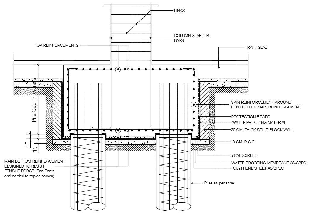
According to Kingspan Insulation operations manager Joe Condon, the design of the system varies depending on the wall loadings. For instance, the version designed primarily for a timber or steel frame construction has both an inner and an outer ring beam — one for the frame, and one for an external leaf of block or brick — that are both thermally isolated from the floor slab.
“While it looks like a raft, it is not an actual raft as the ring beam supporting the walls is separate from the floor slab,” he said. But the ground preparations are essentially the same as those for a raft foundation, in that the site is stripped and made totally level with a uniform layer of stone over the entire footprint of the house.
Another key player in insulated foundations is Kore, which markets a passive house-suitable insulated foundation system called Kore Insulated Foundation. Technical sales manager Steven Magee is also keen to emphasise that the system in its standard form is not like a traditional raft foundation, but a system in itself.
“The issue is that because they look like a raft foundation, everyone calls them a raft foundation, but from a strictly engineering point of view they are not a raft foundation. They can be designed as a raft, but in their standard form they take elements of a traditional raft and elements of a strip footing foundation. It’s an insulated foundation system.”
1 Detail showing the Isoquick insulated foundation system under a timber frame wall; 2 drawing illustrating the floor-to-wall detail for Kingspan’s Aeroground insulated foundation system; 3 200mm of PIR insulation to provide insulation under the ground floor of a passive house scheme in Essex, which had an innovative approach to a traditional strip footing.
Like the Kingspan version, EPS 300, with its high compressive strength, is used in conjunction with concrete and steel, while EPS 100 is used in three layers for the floor insulation. Depending on the design, there can be one or two ring beams involved, for instance to carry an inner or outer leaf.
There are a number of other systems based on a similar principles, such as Viking House’s Passive Slab and Castleform’s Raft Therm. But another household name in insulated foundation systems is Isoquick, which has no qualms about describing its product as genuinely raft-based.
Jonathon Barnett of Isoquick insists that, structurally, a raft is very different to a ring beam with a connected floor slab. “The ring beam design carries all of the load down through the narrow strip around the perimeter, with a thin layer of concrete in between the beams. This concentrates the load on a narrow strip of insulation, limiting the amount of load that can be carried.”
He says that a ring beam design is essentially a strip footing with a reinforced beam, which by extension means the ground underneath the beam would have to be prepared to the same depth as a strip footing, although Kore and Kingspan say there is less need to excavate with their systems.
“Designing the slab as a flat raft means that the load from the walls is spread out, thereby enabling the foundations to be built where ground conditions are softer or more clayish,” said Barnett. “It also simplifies the reinforcement design, removing or greatly reducing the need for time consuming wired cages of reinforcement.”
A genuine raft design also works better thermally, too, he says, not least because the level of insulation under the edge of the slab remains consistent. Ring beam designs require the concrete slab to be thickened at the edges, meaning that the insulation has to be reduced compared to the middle of the building. “All of our details can be designed to achieve a passive standard at the ring beam,” said Magee.
Arguments about thermal performance aside, perhaps the choice among architects depends more on the versatility of all these systems in terms of accommodating the various different types of structure, but for others the appeal of a flat raft system may well be its inherent simplicity in terms of ensuring optimal thermal performance.
Another factor, of course, is cost. Insulated foundation systems may cost more materially, but one argument is that they require far less soil or ground excavation than traditional foundations, including the need to dig up trenches, which in turn speeds up construction and cuts down the risk of health and safety issues.
“Removing the muck is simple and straight forward without the trenches,” said Barnett. “Likewise the sub base and levelling stone take only a day or two to prepare. Once the stone is in place your site is out of the mud making life easier for everyone working on the job. From an empty site to a finished floor is usually less than two weeks. We win contracts simply on the muck away savings alone.”
Structural engineer Hilliard Tanner is also of the view that overall, the costs even out between insulated and non-insulated systems. “We have done a number of insulated foundations that work out cheaper overall than traditional strip foundations,” he said. Insulated foundation systems are certainly attracting more attention from bigger contractors, “because they work really well with modular housing as well and builders like the idea of reducing the skilled labour required on site”, says Steven Magee of Kore.
1 Foundation detail at Denby Dale, the UK’s first certified cavity wall passive house, with a lightweight insulating concrete block at the wall-to-floor junction; 2 Xtratherm detail showing upstand of insulation around the edge of the floor slab to minimise thermal bridging with the inner leaf of the cavity wall; 3 200mm Kingspan insulated strip foundation with 70mm upstand to edges under a passive house in Inverin, Co Galway; 4 this passive house in Co Meath has a strip foundation with 200mm Xtratherm under the concrete slab, which also encases the underfloor heating pipes, and Quinn Lite thermal block at the wall-to-floor junction.
There is also the reduction in concrete use with insulated foundations. “From a cost point of view, you use a lot more polystyrene than you would in a traditional foundation, but that is offset by using approximately 50pc less concrete,” Magee adds.
Furthermore, there is an element of pre-fabrication with such systems in that you are more likely to see the exact specifications of the foundation upfront, including the amount of insulation and concrete used. This can minimise the likelihood of mistakes and material wastage on site. “From a QS point of view, it allows them to work out exact quantities of materials that will be needed up front – as opposed to traditional strip foundations where you dig a trench and approximating the amount of concrete required to fill it.” As mentioned earlier, ground conditions remain the biggest factor, meaning that strip or pile foundations may be a better choice when the soil is softer or subject to potential disturbance from nearby tree roots, or if the wall loadings of a given structure are likely to be too heavy in parts, or if the site in question contains aquifers.
Magee says that Kore’s system can be used in almost any ground conditions. “If ground conditions are poor, the system can be designed more like a traditional raft, whereby ground beams and ribs within the slab are incorporated to make the entire system act monolithically. In the case of very poor ground conditions, e.g. on filled ground, the raft can bear onto standard piles, but whilst also maintaining a complete thermal break between the piles (ground) and the raft”. In any case the system needs to be designed by a suitably qualified engineer based on the ground conditions and superstructure.
Strip foundations
While a common refrain among raft foundation advocates is that strip foundations can lead to thermal compromise when compared to insulated foundation systems, Passive House Plus has featured plenty of projects over the years, of various construction types, that have achieved the passive house standard with a traditional strip foundation.
The key is good detailing. This can mean wall insulation that continues down below ground level, reaching down below the floor insulation, and ensuring a sufficient overlap of thermal insulation between the wall insulation and underfloor insulation. Given that ground temperatures below certain depths remain relatively warm compared to external conditions, the absence of insulation beneath the blockwork separating the wall insulation and floor insulation may be a non-issue – if the insulation layer is brought down below the floor insulation level. For instance, leading Irish insulation manufacturer Xtratherm recommend the wall insulation layer being brought down to a depth of 225mm below the floor insulation layer.
Foundation at an A1-rated social housing project by Linham Construction in Dublin, showing 1 Geocell foam glass gravel and aggregate under the concrete slab; 2 followed above by a radon barrier and; 3 225mm reinforced concrete with a power float finish.
If there is insulation on the room side of the wall build-up — for example on the inside of a timber frame —thermal bridging at this junction can be minimalised by, for example, installing an upstand of insulation around the edges of the floor slab that join with the room-side insulation as per the ACDs (Acceptable Construction Details).
Equally, a common detail for masonry projects is to have a low thermal conductivity block at the base of the inner leaf of masonry, where the wall meets the underfloor insulation, to minimise heat loss through this junction. Xtratherm told Passive House Plus it had conducted an extensive thermal analysis of a wide range of products on the Irish market designed to effectively insulate floors and floor/wall junctions.
“Curiously, many of the system suppliers do not quote a resultant Psi value for this junction,” said Mark Magennis, senior technical adviser at Xtratherm. Magennis said that the resultant Psi values from well-detailed insulated strip footings are generally comparable to insulated foundation systems.
“Yes while there can be a reduction in the Psi value with some insulated foundation systems, traditional strip foundations detailing with the use of medium density blocks and careful detailing of conventional insulation also reduces the Psi value,” he said.
The company’s own detail is based on the Irish acceptable construction details (ACDs) and allows for typical compressive loadings for dwellings, and radon detailing in accordance with Irish EPA guidelines.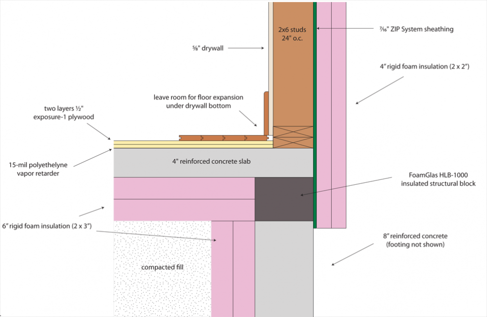
“It can also dispense with the requirement for bespoke engineering calculations as required with foundation systems,” Magennis said. The detail employs the company’s CavityTherm Foundation Riser boards in the cavity, extending below the damp proof course (DPC), ensuring at least 225mm overlap from the top of the floor insulation. It features a radon barrier dressed across the cavity, dissecting or weaving under the insulation and then extending under the floor insulation.
Magennis said that for anyone looking to decide on a foundation system, the key thing is that the performance of products and system is clearly defined, and performance claims are published and certified by a suitably qualified person – such as an NSAI-registered thermal bridging modelling assessor – in a way that is easy to understand. He also emphasised the need for “better and easier detailing on site”.
Another alternative to insulated raft or strip foundations is Geocell, a foam glass gravel material that works as a lightweight exterior insulation and sits below the floor slab. It is load-bearing, with a comparable compressive strength to a hard-core, and free-draining. The system is passive house certified and offers similar thermal performance to mainstream insulation systems, with a lambda value of 0.08 W/m2K. It is made entirely from recycled glass, and distributed in Ireland by Linham Construction.
Retrofit
Of course it’s probably no surprise to learn that, short of lifting up the entire building, it’s practically impossible to retrofit insulated foundation systems.
But there are some measures that can be reasonably cost-effective to implement, such as digging out the ground floor and adding insulation. “What you’d be doing there is to dig out the floor down to a level that would be compact enough to create a level base, put in your insulation and put down a floor slab and put a slip of insulation around the perimeter to create a cold bridge divider between the floor slab and the lower part of the inside wall,” said Joe Condon of Kingspan.
The biggest issue would be waterproofing and keeping the load-bearing structures in place while you rip up the floor.
Another step might be to bring external insulation down below ground floor level to address thermal bridging. Sometimes, just bringing external insulation deep enough down underground will be sufficient as, once you get below certain depths, ground temperatures pick up anyway.
Radon barriers
In areas that have been listed as having high radon levels, Irish and UK building regulations generally stipulate that new buildings should be fitted with a strong radon barrier and sump, while areas less affected may still need some basic protective measures.
According to Hilliard Tanner, with insulated foundation systems as he details them, the radon sump goes into the top of the fill as normal, and then barriers are placed under the insulation, and leaving it out past the sides of the insulation. Alternatively, you could run the barrier on top of the first or second (of the three) layers of floor insulation, then in contact with the ring beam.
-
Foundation at an A1-rated social housing project by Linham Construction in Dublin, showing Geocell foam glass gravel and aggregate under the concrete slab
Foundation at an A1-rated social housing project by Linham Construction in Dublin, showing Geocell foam glass gravel and aggregate under the concrete slab -
-
-
Radon barrier
Radon barrier -
Pouring a concrete slab over Xtratherm insulation with an upstand of insulation around the edges
Pouring a concrete slab over Xtratherm insulation with an upstand of insulation around the edges -
The floor slab poured
The floor slab poured -
225mm reinforced concrete with a power float finish.
225mm reinforced concrete with a power float finish. -
An Isoquick passive slab foundation at the landmark passive-certified UEA Enterprise Centre
An Isoquick passive slab foundation at the landmark passive-certified UEA Enterprise Centre -
Foundation detail at Denby Dale, the UK’s first certified cavity wall passive house, with a lightweight insulating concrete block at the wall-to-floor junction
Foundation detail at Denby Dale, the UK’s first certified cavity wall passive house, with a lightweight insulating concrete block at the wall-to-floor junction -
Detail showing the Isoquick insulated foundation system under a timber frame wall
Detail showing the Isoquick insulated foundation system under a timber frame wall -
Aerial view of a KORE Insulation foundation system with two ring beams
Aerial view of a KORE Insulation foundation system with two ring beams -
00mm Kingspan insulated strip foundation with 70mm upstand to edges under a passive house in Inverin, Co Galway
00mm Kingspan insulated strip foundation with 70mm upstand to edges under a passive house in Inverin, Co Galway -
Isoquick insulated foundation system on the passive-certified Lansdowne Drive, London.
Isoquick insulated foundation system on the passive-certified Lansdowne Drive, London. -
This passive house in Co Meath has a strip foundation with 200mm Xtratherm under the concrete slab, which also encases the underfloor heating pipes, and Quinn Lite thermal block at the wall-to-floor junction.
This passive house in Co Meath has a strip foundation with 200mm Xtratherm under the concrete slab, which also encases the underfloor heating pipes, and Quinn Lite thermal block at the wall-to-floor junction. -
150mm Xtratherm insulation laid under the floor slab of Ireland’s first passive house pharmacy, on a tight site in Tipperary
150mm Xtratherm insulation laid under the floor slab of Ireland’s first passive house pharmacy, on a tight site in Tipperary -
Geocell, a foam glass gravel material that is both load-bearing and insulating
Geocell, a foam glass gravel material that is both load-bearing and insulating -
200mm of PIR insulation to provide insulation under the ground floor of a passive house scheme in Essex, which had an innovative approach to a traditional strip footing
200mm of PIR insulation to provide insulation under the ground floor of a passive house scheme in Essex, which had an innovative approach to a traditional strip footing -
Xtratherm detail showing upstand of insulation around the edge of the floor slab to minimise thermal bridging with the inner leaf of the cavity wall
Xtratherm detail showing upstand of insulation around the edge of the floor slab to minimise thermal bridging with the inner leaf of the cavity wall -
Kingspan’s Aeroground EPS-insulated foundation system cut for double ring-beams to support the inner and outer leaf of a cavity wall;
Kingspan’s Aeroground EPS-insulated foundation system cut for double ring-beams to support the inner and outer leaf of a cavity wall; -
XPS insulation laid on the excavated ground floor of Ireland’s first certified passive house retrofit project, designed by PH+ columnist Simon McGuinness
XPS insulation laid on the excavated ground floor of Ireland’s first certified passive house retrofit project, designed by PH+ columnist Simon McGuinness

View the embedded image gallery online at:
https://passivehouseplus. ie/magazine/guides/the-ph-guide-to-insulating-foundations#sigProId609cd85f7e
How to make an insulated Finnish foundation | Experts
Usmanov Pavel Alekseevich
architect
Absolute – this is how you can characterize the technology of the insulated Finnish foundation in matters of energy saving. After all, such a foundation of the house is able to withstand the most severe frosts without any problems.
Although the advantages of this constructive solution are not limited to this only … You just need to make it right, taking into account all the nuances. The Lesobirzha company will help you with this: we will create a turnkey UFF foundation – and with a quality guarantee.
What will you learn in the article?
- All the pros and cons of the insulated Finnish foundation
- How is UVF created?
- What are the advantages of choosing Lesobirzha services?
All the pros and cons of the insulated Finnish foundation
Words about the absolute characteristics of the UVF are almost no exaggeration. It has several undeniable advantages:
- High energy saving. The Finnish people know everything about the cold. Therefore, the thermal insulation of the foundation invented by them is complete, and it is not difficult to further strengthen it if necessary.
- Easy to level up. It is possible to seriously increase the height of the UVF, adapting it to the relief or climate (which, by the way, is not allowed by the insulated Swedish stove similar in technology).
- Durability. You can build any house on such a foundation – even a frame house, even a brick one, even a small one, even a huge one with 3 floors. In all cases, the base has a resource of decades.
Although we do not want to mislead you, the technology is not perfect. Therefore, it is worth considering its negative aspects:
- Cost. Be prepared for the fact that the UFF foundation has the highest price. The reason for this: rather laborious installation and high consumption of building materials.
- Solid base. The created platform is monolithic – it is practically impossible to organize a basement under it, or even a basement floor, which limits some of the projects.
- Complexity of repair. All communications are laid inside the UFF. For this reason, it is rather problematic to change them after a while to meet new needs, and even more so to repair them.

How is UVF created?
The construction of insulated Finnish foundations must be consistently, carefully performed – stage by stage:
- Start. All work begins with a “cushion”. To do this, they dig a pit clearly according to the size of the future building and completely cover it with geotextiles to protect the underground part from freezing and moisture. Then it is filled with seeded sand, and in layers of 10-15 cm and carefully tamping it to obtain a denser base.
- Building a plinth. The construction of an insulated Finnish foundation is largely characterized by this particular element. First, reinforced concrete tape with a cross section of 60×20 cm is poured along the perimeter and along the load-bearing walls. When it has dried, row after row, expanded clay-concrete blocks are laid on it according to the desired height of the plinth.
- Thermal insulation. In order to qualitatively insulate the UVF, several actions are carried out. First: laying expanded polystyrene on the back side of the KBB wall with a layer of up to 10 cm. Second: filling the remaining free space with seeded sand (also in layers and with tamping). Third: closing the sand part from above with PPS sheets up to 20 cm.
- Installation of communications. In fact, such procedures are carried out gradually in the past stages. So, the drainage system of the site is hidden in the lower layers of sand. Pipes of cold water supply and sewerage are placed in the upper sand filling. And hot water goes already inside the “cover” of Styrofoam under the floor.
- Filling the floor. The turnkey construction of the UFF foundation is impossible without this task. First, the PPS layer is hidden with a metal reinforced mesh. Then pipes of a water-heated floor are laid on it and a screed is poured. After curing, it needs to be polished with a special grinder – this will make the surface almost perfectly smooth.
- Finish. At the end of all work, storm water inlets, storm water are installed, waterproofing of the plinth from expanded clay concrete is carried out. A blind area is also being built around the perimeter of the cottage: it is tightly rammed and insulated with polystyrene foam. The last detail is the decorative design of the basement part of the actually finished UFF.
 First, reinforced concrete tape with a cross section of 60×20 cm is poured along the perimeter and along the load-bearing walls. When it has dried, row after row, expanded clay-concrete blocks are laid on it according to the desired height of the plinth.
  The turnkey construction of the UFF foundation is impossible without this task. First, the PPS layer is hidden with a metal reinforced mesh. Then pipes of a water-heated floor are laid on it and a screed is poured. After curing, it needs to be polished with a special grinder – this will make the surface almost perfectly smooth.
 What are the advantages of choosing Lesobirzha services?
- Competent craftsmen. We do not work with seasonal workers – we have a long-established team of specialists: qualified and experienced. They will professionally and accurately perform all the work on the construction of the UVF for your private home within the agreed time frame.
- Proven materials. We carry out every construction of insulated Finnish foundations using high-quality “raw materials”. We include class B25 concrete based on Portland cement (previously: M350 grade), extruded PPS, fine sand, geotextiles, etc. to it.
- Continuous monitoring. Although all the actions of the foremen at the facility are described in job descriptions and project specifications, we constantly monitor how the work is going. At the same time, we have no secrets – you will receive detailed reports on each stage of the construction of your UVF.
- Advanced service. With us, you can go beyond just foundations – our company is able to implement any project from A to Z. Designing houses of various types, construction, exterior, interior decoration, other objects on the site – the choice is not limited.
- Company warranty. Since 2010, our specialists have already implemented hundreds of diverse projects – and you can easily verify their quality after a while. Therefore, we are confident in the quality of services and provide a guarantee for all work from 1 to 5 years.
- Transparent budget. As already noted, the price for the UFF foundation is not the lowest – but with us it is always justified to the last ruble. We respect you, so the cost of the final product is competitive and open so that you know what you are paying for.

 Therefore, we are confident in the quality of services and provide a guarantee for all work from 1 to 5 years.
 Contact the Lesobirzha company: together we will find the best solutions for building your home in Moscow, St. Petersburg and other regions of Russia – with the best possible foundation!
See how we can
June 24, 2020
865
Fixing the walls of the first floor behind the handles and completing the second floor ourselves
10.0×11.2 m
36 days
KP “Green Quarter”
June 22, 2020
911
Assembling a frame house for finishing at Vyazemskoye
7. 1×11.6 m
2 300 000
KP “Vyazemskoe”
April 25, 2019
1635
Chalet-style house with turnkey finishing in Forest Landscape
7.9×8.9 m
6 700 000
51 days
KP “Forest Landscape”
December 10, 2018
2269
Private gym – new build
6.3×9.5 m
21 day
KP “Zaokskie open spaces”
January 30, 2018
1729
How we helped the customer to realize his dream of a country house, and even save money in the future
6. 9×8.9 m
5 800 000
60 days
SNT “Vika”
Next
See other works
Lesobirzha recommends
Whole catalog
Insulated Finnish foundation price in St. Petersburg and Leningrad Region
We will talk in detail about the insulated Finnish foundation, as the name implies, this type of foundation came to us from a neighboring country – Finland. At its core, this foundation is a comprehensive solution that provides a ready-made zero cycle at the stage of foundation work.
The advantage of this solution is precisely the integrated approach to the construction of the foundation of the house, that is, at the stage of foundation work, we receive not only the foundation of the house, but also a set of engineering solutions. It is important to understand that for the construction of this type of foundation, a set of design solutions is needed at the very beginning.
Such as:
- Architectural solutions (AR) with the layout of the house;
- Wooden construction sections (CD) concerning frame houses, wooden houses and SIP houses;
- Reinforced concrete structures (RC) in heavier houses.
Photo UFF1
Photo UFF1
Photo UFF2
Photo UFF2
Part of the project, architectural solutions and house layouts are necessary in order to accurately implement the distribution of communications around the house. Such as underfloor heating as a heating system, such as hot and cold water pipelines, sewage pipelines. Also, if at the foundation stage there is a project for the power supply of the house and a design project, then at the stage of foundation work it is possible to implement the installation of rough electrics. Immediately before the construction of the foundation, it is necessary to carry out earthworks using a backhoe loader, which ensure the selection of the vegetation layer under the building spot. After the operation of the excavator loader, the house is marked in the pit, then with the help of compacted sand, a flat platform for receiving concrete is provided under the base of the house. The next stage in the construction of the insulated Finnish foundation is the installation of the basement of the house from expanded clay concrete blocks, 300 mm thick, 200 mm high, the number of rows of expanded clay concrete blocks is 3.
With such a number of rows of basement blocks, the height of the visible part of the basement from the level of the blind area of the house to the facade of the house is 400 mm. In cases where there are height differences under the building spot or there is a desire to increase the height of the finishing part of the base, this is easily solved by increasing the number of rows of blocks. Also, the scope of foundation work always includes a hidden storm sewer along the perimeter of the house and a drainage system, if necessary. A prerequisite for the resistance of the foundation of the house from the forces of frost heaving is the insulated hidden blind area of the house due to the fact that this type of foundation is shallow-buried, it is necessary to ensure that there is no freezing under the sole of the foundation. This event is achieved by installing polystyrene foam 50 mm thick with a width of 1200 mm. An important point in protecting the underground part of the foundation is waterproofing. In this case, coating waterproofing is used, and waterproofing is applied on top with rolled material.
Photo UFF3
Photo UFF3
Photo UFF4
Photo UFF4
An additional advantage of this type of foundation, in comparison with foundations made of fixed formwork, is that the visible part of the basement can be without finishing for quite a long time. A wide range of materials can be used as a finish on the visible part of the foundation plinth. From ordinary paint to mosaic plasters and stone surfaces in the form of clinker. A distinctive feature of this type of foundation is also the fact that the basement part of the house is insulated from the inside of the basement. Thus, we provide a finishing finish on the concrete surface, which is most often preferable and more durable. The laying of basement blocks is carried out on a cement-sand mortar of at least 200 grades. After the organization of the outer perimeter of the foundation of the house, that is, the installation of the sole of the house made of reinforced concrete, the installation of the basement of the house, the implementation of drainage work, the implementation of storm sewers and the recessed blind area of the house, we proceed to the organization of floors on the ground.
The organization of floors on the ground begins with layer-by-layer tamping with sand in a mechanized way to the design mark, the thickness of the sand layers is about 200 mm, then sewerage pipes are installed in the sand backfill at design points. After the installation of sewer pipes, insulation is installed under the base 200 mm thick from expanded polystyrene. Also a very important point at this stage is the organization of reinforcement in the house screed under heavy loads, such as load-bearing partitions, or heavy stoves and fireplaces. Also an important point at this stage is the choice of the correct brand of expanded polystyrene in accordance with the loads. In places under the floor screed where domestic loads are present, it is necessary to use expanded polystyrene of at least 6-8 kN per m2 at 10% linear deformation. Places where large loads are concentrated must be considered separately, but often the grade of expanded polystyrene starts from 14-16 kN per m2 with the same 10% linear deformation, also in highly loaded places there is working reinforcement in the floor screed, the diameter of the reinforcing mesh is 6 mm, the mesh size is 100 mm .
Also, between the layers of insulation under the floor screed, pipes for cold water supply and hot water supply are installed at design points, and where necessary, hot water supply is recirculated. The final stage before accepting a concrete floor screed is the installation of pipelines for a water-heated floor as the main heating system for a house. The diameter of the pipe used in the project is 16mm, and the pipe material is heat-resistant polyethylene. The method of laying a warm floor is a snail, the pipeline pitch is 150 mm, in areas with increased heat loss it reaches 100 mm. In each project of this type of foundation, it is mandatory to install ladders, ladders are constantly in operation, for example, in showers of a building design or emergency ladders. Usually they are located in the area of the boiler room in case of a leak, in the drains with constant operation a wet seal is used, and in the emergency drains a dry seal is used. At the end of the whole complex of foundation works, the final floor screed is received, the thickness of the concrete of the floor screed is 10 cm, in places of reinforcement 20 cm, the concrete grade is 400ya. On this foundation, the expected volume of floor screed concrete is approximately 11 m3.
 It should also be noted that concrete work carried out at near zero temperatures or negative temperatures must be accompanied by the organization of so-called greenhouses. In which a stable positive temperature is provided in one way or another. At the end of all work on the foundation, the final grouting of concrete is carried out.
A feature of this insulated Finnish foundation is the fact that the facade of the house will be made of facing bricks and that the house itself will be built using sip technology. Surely the viewer had a question about the construction on which I am now. In this house project there will be a large terrace, but the customer decided to implement it in the form of a concrete slab. For those who want to independently implement the UFF on the forum house, there is a lot of information in the corresponding section, but the main advice for the implementation of this type of foundation, just like for other foundations that provide a ready-made zero cycle, is a very detailed study of planning solutions, architectural solutions to ensure accurate installation of all engineering systems that are included in this type of foundation. In each project of this type of foundation, it is mandatory to install ladders, ladders are constantly in operation, for example, in showers of a building design or emergency ladders. Usually they are located in the area of the boiler room in case of a leak, in the drains with constant operation a wet seal is used, and in the emergency drains a dry seal is used. At the end of the whole complex of foundation works, the final floor screed is received, the thickness of the concrete of the floor screed is 10 cm, in places of reinforcement 20 cm, the concrete grade is 400ya. On this foundation, the expected volume of floor screed concrete is approximately 11 m3. It should also be noted that concrete work carried out at near zero temperatures or negative temperatures must be accompanied by the organization of so-called greenhouses. In which a stable positive temperature is provided in one way or another. At the end of all work on the foundation, the final grouting of concrete is carried out.
 A feature of this insulated Finnish foundation is the fact that the facade of the house will be made of facing bricks and that the house itself will be built using sip technology. Surely the viewer had a question about the construction on which I am now. In this house project there will be a large terrace, but the customer decided to implement it in the form of a concrete slab. For those who want to independently implement the UFF on the forum house, there is a lot of information in the corresponding section, but the main advice for the implementation of this type of foundation, just like for other foundations that provide a ready-made zero cycle, is a very detailed study of planning solutions, architectural solutions to ensure accurate installation of all engineering systems that are included in this type of foundation.
Insulation of a shallow foundation with expanded polystyrene. Insulation Penoplex® Foundation
Arrangement technology
Small strip foundation (LFMZ) is a common type of foundation in all climatic regions of Russia.
The strip foundation made of monolithic reinforced concrete is simple in execution, there are no seams in it, its structure is homogeneous, which is very important for buried structures.
The strip foundation of a small foundation is located at a depth of 30-40 cm. In order for the foundation under the foundation to be in an unchanged state, the heaving soil is replaced with non-heaving one: crushed stone with sand.
For all types of strip foundations: with a ventilated underground and with floors on the ground, effective thermal insulation from high-quality extruded polystyrene foam PENOPLEX FOUNDATION ® is used. Strip foundations in the case of execution with floors on the ground, have vertical insulation located on the outer side from the base to the mark of the end of the base and are a heat insulator. The insulation of the blind area of the strip foundation is placed horizontally at the level of the base of the foundation. The colder the climate, the wider the blind area should be and the thicker its layer should be.
Calculation and design rules
The design of a small strip foundation should be carried out by designers with the appropriate knowledge and qualifications. As a basis, they make a decision that will satisfy in terms of reliability, ensure the durability and cost-effectiveness of the structure at all stages of construction and operation.
Foundations are designed on the basis of regulatory documents and taking into account:
Results of engineering-geological and hydro-geological surveys for the construction site;
Climatic conditions of the construction area;
Loads acting on foundations;
Technical solution for low-level strip foundation from PENOPLEX®
PENOPLEX® – for small strip foundations (LFMZ)
In most of Russia, in winter, the soil freezes to a depth of 2. 5 meters.
Residents of country houses often face the phenomenon of frost heaving. Frost heaving is an increase in the volume of wet soil due to its freezing.
At negative temperatures of atmospheric air, the volume of wet soil increases in volume during freezing. For example, clay can rise by 10-15%. The forces of frost heaving act on the structure unevenly – the lifting of the soil under different parts of the foundation can be carried out to different heights.
The probability of frost heaving depends on the type of soil, its physical and mechanical characteristics, climatic features, groundwater level, type of foundation.
Under the action of large loads from the soil, the foundation can rise, deform with the formation of cracks and possible subsequent destruction of the foundation. To minimize the impact of soil heaving on the foundation, you can place drainage and an insulated blind area around the perimeter of the house. It will not allow the soil to freeze in the area of \u200b\u200bthe foundation tape. PENOPLEX FOUNDATION 9 will help protect underground structures from freezing and frost heaving0218® .
Why is PENOPLEX FOUNDATION® the best solution compared to other materials?
The share of foundations and basement floors accounts for about 10% of all heat losses in a building. Insulation of the buried part of the building in the case of a strip foundation with floors on the ground reduces heat leakage and protects the foundation structure from freezing. Important: the floor structure on the ground must also be insulated to protect against heat loss.
Highly effective thermal insulation made of extruded polystyrene foam has a high compressive strength at 10% linear deformation and for PENOPLEX FOUNDATION ® is at least 0.3 MPa (30 t/m 2 ).
Thermal insulation boards made of extruded polystyrene foam are absolutely stable in terms of geometric dimensions and physical properties.
An important characteristic of PENOPLEX FOUNDATION ® boards is almost zero water absorption. This means that the construction of the foundation and the future house is reliably protected from moisture from the ground and air. Effective insulation will prevent cracks, deformation and destruction.
Insulation PENOPLEX FOUNDATION ® has high heat-shielding characteristics – the thermal conductivity of the material is not more than 0.034 W/m∙°C.
Thermal properties are unchanged throughout the entire service life, which is more than 50 years.
Thermal insulation of shallow foundations with PENOPLEX
When erecting shallow foundations (MSF) on heaving soils, which are widespread in Russia, certain difficulties arise. The process of soil heaving can lead to deformation of the building if it is built on the MLF. Due to the excessive expansion of groundwater during its freezing or the formation of an ice lens in moist, frost-susceptible soil, frost heave forces arise that push building structures. However, using heat flows, it is possible to bring the boundary of soil freezing beyond the base of the foundation by changing the thickness and width of the thermal insulation. Relevant construction technologies were developed by PENOPLEX SPb LLC. The company presents ready-made optimal solutions that make it possible to equip shallow foundations on heaving soils with seasonal freezing.
Thermal insulation of shallow foundations
The use of high-quality thermal insulation PENOPLEX ® GEO from extruded polystyrene foam allows you to isolate the base of the foundation from the forces of frost heaving and set the minimum laying depth, regardless of the estimated freezing depth.
The design of shallow foundations on heaving soils is carried out in accordance with SP 50-101-2004 “Design and installation of foundations and foundations of buildings and structures.”
For the effective use of PENOPLEX ® GEO boards in the design under consideration, STO 36554501-012-2008 “Use of thermal insulation from PENOPLEX foamed polystyrene foam boards in the design and installation of shallow foundations on heaving soils” was created. The standard was developed by specialists of NIIOSP named after V.I. N.M. Gersevanova – a branch of the Federal State Unitary Enterprise “Research Center” Stroitelstvo “, taking into account the experience of using heat-insulated shallow foundations in America and Europe, as well as the features of engineering-geological, hydro-geological, climatic conditions and the experience of building low-rise buildings in Russia.
Advantages of PENOPLEX
® in relation to thermal insulation of building foundations
- Thermal conductivity coefficient – 0.034 W/m•K
One of the lowest among the heaters used in construction- High strength PENOPLEX ® GEO boards have a compressive strength of at least 0.30 MPa (30 t/m 2 )
- Zero water absorption
Consistently high heat-shielding properties. Possibility to store boards without weather protection- Easy and safe installation Convenient panel geometry, easy handling and installation
- Mounting in all weather conditions
- L-shaped edge on all sides of the plate
Allows boards to be joined tightly without thermal bridges- Absolute biostability
Safe in contact with water and soil.- Safety
Does not contain fine fibers, dust, phenol-formaldehyde resins, soot, slags. Mounting without respiratory protection- Environmentally friendly Safe raw materials, manufactured using advanced CFC-free technologies.
- Durability over 50 years Test report NIISF RAASN No. 132-1 dated October 29, 2001
 Not a matrix for the development of unwanted microorganisms
 Structural solutions for thermally insulated shallow foundations using PENOPLEX®GEO 9 slabs0022
Heated building foundation:
- Building wall
- Floor structure
- blind area
- PENOPLEX® GEO
Heated building foundation with technical underground
- Building wall
- Building floor
- Protective layer
- Vapor barrier
- blind area
- Foundation
- PENOPLEX® GEO
- Non-rocky soil
Unheated building foundation:
- Building wall
- Floor structure
- blind area
- Foundation
- PENOPLEX® GEO
Foundation of a periodically heated building (e. g. summer house):
- Building wall
- Floor structure
- blind area
- Foundation
- PENOPLEX® GEO
Foundation of a cold extension (e.g. porch):
- Wall of an existing heated building
- Extension wall
- Foundation of an existing building
- Extension foundation
- PENOPLEX® GEO
- Sheet material (OSB/plywood)
Foundation of a free-standing support:
- Support
- Waterproof layer
- Foundation
- PENOPLEX® GEO
- Sand and gravel mix
Band support foundation:
- Wall
- Strip foundation
- blind area
- PENOPLEX® GEO
- Sand and gravel mix
Insulated Swedish slab foundation – description, production
Insulated Swedish Plate (UShP) is one of the types of shallow foundations.
Ready-made UWB foundation on the site
UWB is a foundation structure where complete engineering preparation has been made for connecting the functioning systems of a low-rise residential building.
In addition to optimal strength characteristics, such a foundation has effective thermal insulation of the outer contour from the side of the ground and along the perimeter of the reinforced concrete slab.
At the “Swedish plate” subsequent work on the device of various backfills, additional thermal insulation, drilling of holes, and the installation of additional concrete screeds are excluded. In the complex of work performed, their cost is 15-20% lower in comparison with traditional foundations with the same configuration. However, a prerequisite for the construction of the “Swedish slab” is the need to complete the development of all engineering systems, interior design and landscape design before construction begins.
It will not work to build a box at home and then calmly engage in the design of engineering systems. “Swedish plate” is a foundation made according to carefully verified drawings. At this stage, calculations should be made not only for building structures, but also for heating, ventilation, hot and cold water supply, a built-in vacuum cleaner, etc. Alterations and corrections of the “Swedish plate” are not allowed.
Thus, if you perform a comprehensive design of the future house and at the same time choose the UWB as the foundation, you get a fully prepared structure for exterior and interior decoration, with the ability to connect all the life support systems of a country house, with significant savings, of higher quality.
UShP construction procedure
UWB base device
Excavation
The foundation of the foundation pit is one of the most important stages. It should be even and uniform.
The soil-vegetative layer of the earth is removed according to the preliminary breakdown of the building on the land plot. The gravel-sand base is poured and compacted, drainage is performed along the perimeter of the foundation.
It is necessary to pay attention to the accuracy of the excavation to the design mark and protection against waterlogging during the construction process and the quality of the layer-by-layer compaction of the base. Refinement to the mark of the bottom of the excavation of the excavation is recommended to be done manually in order to prevent loosening of the mainland soil.
All elevation marks of the pit are controlled by a level.
Removal of the fertile layer when preparing the foundation of the UWB with an excavator
Drainage device
Foundation drainage eliminates the risk of excess moisture getting under the base of the slab.
A drainage trench is made with a slope towards the drainage of water from the site. A geotextile sheet 3 meters wide is laid on the bottom of the drainage trench.
Next, the base is filled with crushed stone. On the prepared base, the drainage pipe is laid. Drainage revision wells are installed in accordance with the project.
The pipe is covered with crushed stone and wrapped with the edges of the geotextile sheet free from filling.
Drainage system around the perimeter of the excavation
Construction of crushed stone and sand base
The base transfers the load from the slab to the ground and vice versa, the density must comply with the standards and be uniform and even over the entire area.
Geotextiles are laid over the entire excavation area with release onto the walls of the pit. Foundation preparation may include crushed stone, sand, ASG and other materials, in accordance with the constructive solution of the working project.
The base material is laid on geotextiles and compacted in layers with vibro-tampers. The material is additionally moistened before compaction. The backfill level is controlled by a level and smoothed out to create a flat surface so that the thermal insulation is laid tightly, without air gaps.
Sand compaction with tamper
Thermal insulation of the slab and laying of communications
Installing the L-block
Along the perimeter of the UWB, L blocks are installed that perform the function of a fixed formwork, which will later be the basement of the building. The connection between L blocks is carried out with polyurethane foam glue and plastic fasteners for thermal insulation.
L-block
Installation of L-block formwork
The characteristics of thermal insulation in the places of support of load-bearing walls are determined by a constructive design calculation.
(If L blocks are not made, then wooden formwork will be required, which will increase the time and cost of the work).
|
Indicator name |
The value of the indicator for slabs of brand | |||
|
PPS 30 |
PPS 35 |
PPS 40 |
PPS 45 |
|
|
Density, kg/m, not less than |
30 |
35 |
40 |
45 |
| Compressive strength at 10% linear deformation, kPa, not less than | 200 | 250 | 300 | 350 |
| Bending strength, kPa, not less than | 400 | 450 | 500 | 550 |
| Thermal conductivity of boards in a dry state at a temperature of (10±1)°C (283 K), W/(m K), no more than |
0. 035 035 |
0.036 | 0.036 | 0.036 |
| Thermal conductivity of boards in a dry state at a temperature of (25±5)°C (298 K), W/(m K), no more than | 0.037 | 0.038 | 0.038 |
0.038 |
|
Humidity, % by mass, no more than |
1.0 |
1.0 |
1.0 |
1.0 |
|
Water absorption for 24 hours, % by volume, no more than |
1.0 |
0. |
0.3 |
0.2 |
|
Self-burning time, s, no more than |
4 |
4 |
4 |
4 |
 5
5 Table of heaters used for UWB – excerpt from GOST 15558-2014.
A polyethylene film is laid on the sandy base, on which the first L blocks are installed, forming the corners of the building, then ordinary blocks.
Communication device
At the same time, a communication device is being installed, which are located under the thermal insulation. For this, trenches are dug for sewerage, water supply, electric cable and other inputs and outputs.
After laying utilities, the base is compacted and leveled so that the thermal insulation can be laid tightly, without air gaps.
Communication wiring for UWB device
Laying thermal insulation
The stacked sheets of medium-density thermal insulation form a block between the supporting beams, which are intended for a power screed. Sheets are laid in layers, with dressing of the seams of adjacent sheets and vertically fastened with special plastic fasteners that are long enough to fix all layers of thermal insulation. (The vertical seams of the layers of the laid thermal insulation must not coincide).
Laying thermal insulation on the base of the slab
Reinforcement of reinforced concrete slab
Arrangement of the frame of reinforced concrete beams
First, a frame is made for reinforced concrete beams from longitudinal reinforcement and bent transverse clamps of class A3. The diameter and pitch of the longitudinal and transverse reinforcement is determined by the design decision and depends on the ultimate loads of the load-bearing walls on the foundation. Finished frames are installed on special plastic clamps that provide a protective layer of concrete. The corners of the frame are connected by L-shaped reinforcement bars with an overlap of 50 diameters of the reinforcement used.
Foundation beam reinforcement
Reinforcement of concrete screed
Reinforcement with underfloor heating
Next, a vertical lower reinforcing mesh of the foundation power screed with a cell of 150×150 mm is installed, to which a plastic pipe for water heating of a warm floor is fixed with plastic clamps. The pipes are additionally protected by a heat-insulating shell at the points of passage through the load-bearing walls. The pitch of the turns of the plastic pipe and their location in the plan are also determined by the working draft of the UWB.
Completion of the reinforcement volume of the UWB with the output of the contours in the manifold
After installing the underfloor heating, the upper grid of the concrete screed with a cell of 150 x 150 mm is installed.
Reinforcement diameters are determined by calculation in the working design of the UWB.
All pipes for water heating and water supply are collected in collectors.
Laying of electrical cables, built-in vacuum cleaner systems, ventilation ducts, piping of heat pumps, etc., is carried out in accordance with the design of heating, ventilation, water supply systems, etc.
After assembly, these systems are pressed and remain under pressure until the end of the concrete pour.
Ready frame for pouring concrete
Concreting UShP
Concreting Swedish slab
Concrete supply and distribution in the formwork of the UWB slab
Concrete of a given grade is placed using a deep vibrator.
For high-quality alignment, a vibrating rail is used, the filling level is controlled by a level.
Surface grouting
Concrete grouting of the UWB slab surface
Depending on weather conditions. the concrete must stand for some time to set and be walkable, but the plasticity would be sufficient to be machineable with a power trowel.
Concrete care
Moistening of the slab during curing of concrete
After laying, the concrete is maintained so that it is constantly wet. This is necessary to set the strength of concrete and avoid adverse effects.
Ready-made foundation insulated Swedish slab
foundation construction technology based on Finnish technology – Lumi Polar, Russia
We, Finns, have excessive requirements for foundations, which are justified by experience, proven by time and reflected in Finnish standards for their design and production. We will briefly explain why they cannot be retreated from and what will happen to the house if they are neglected.
Everything rests on the foundation!
The reliability of any home is, first of all, the reliability of the foundation. All structures are assigned to it, therefore, any, even the most insignificant deviations from the standards or errors made during its installation – firstly, it will be impossible to fix it later, and secondly, over time lead to the biggest problems with the house.
Foundation cost
Here it is important to understand for which particular foundation you were quoted the price. The foundation can be installed for 3 kopecks by simply throwing a slab on the damp earth and at the same time the earth is not drained, and the foundation is not insulated or poorly insulated.
For example, to keep the house warm, and your money for heating does not flow through the cold foundation “into the sand” – according to our Finnish standards, we insulate it with foam around the perimeter (thermal liners) with a thickness of 100 mm, and the insulation of the foundation slab is 300 mm
Others – the thickness of the insulation of the entire foundation is 100 mm, max 120 mm – the standard, which is 3 times lower, and therefore, over time, problems with the house + huge overpayments for heating
When we talk about the cost of our UWB (Insulated Swedish Board) or UPF (Insulated Finnish Foundation) and what they depend on, many people exclaim: No, yours is expensive, other UWFs/UFFs are cheaper. Yes, ours is more expensive, but our UWF/UFF foundations are completely different!
- Firstly, as we found out, other companies gave our Scandinavian names UWhP / UFF to their foundations, but for some reason there are no standards for their production and installation, because. a lot of things are wrong or not provided (like as unnecessary)))
- Secondly, if you do not know the specifics of the site, geology data, relief (straight, inclined), when there are no loads on the foundation, you do not know the scope of work, it is impossible to give an exact price. Give only irresponsible companies
- Thirdly, it is long and uninteresting to “burrow” deep into the foundation, therefore, to compare our Scandinavian UWB / UFF with those who call them that, we will give a couple of simple examples
FOR EXAMPLE:
The cost of our foundations includes the cost of not only its production, but also all the activities associated with it. For example, the installation of a drainage system (materials and work), which is integral and, by the way, one of the most important components of foundation production.
Drainage system – especially important Finnish standard
Drainage is the careful installation of a stormwater system, drains, manholes, drains, pipes, and a rubble area around the home. If this is not done when installing the foundation, then over the years moisture will accumulate under the foundation, which will gradually rise into the house.
Moisture penetrating the foundation leads to dampness in the house, which is considered its most dangerous enemy: it leads to damage to structures, the most costly repairs, the emergence of fungus and mold (mold is a serious threat to health, in Finland, when mold appears, houses are demolished, t .to fight it is useless).
It is important not only to carefully install the drainage system, but also to design it correctly. All calculations should be made with a view to the distant future, because. over the years, the capacity of the drainage system can be significantly reduced.
It is worth noting that all Finnish standards are good because they are approved in Finland with increased strength factors and with a view to the distant future – on which reliable Finnish quality is actually built and stands made in Finland
FOR COMPARISON:
For others, installation of a drainage system is not included in the cost of foundations! They consider these activities not related to the foundations, or completely unnecessary, or they offer to carry out after the installation of the foundation, or they say that this is the business of landscapers after the construction of the house, etc.
There are many reasons, but all of them, in our hardened Finnish eyes, are complete nonsense, because they lead the house to the most deplorable consequences …
The cost of our foundations also includes measures for thermal and waterproofing, external filling along the perimeter of the basement and much more – up to the final work on backfilling and compacting the soil surface.
If we do not understand what exactly we are paying for, everything will always be expensive for us!
Since we build foundations only in accordance with our own Finnish standards and rules, the price includes all measures taken in Finland for their installation.
If only the price is decisive for you, and the quality is not important, then, sorry – you are not to us, but our fundamental Finnish advice will definitely come in handy for you.
- If following the installation of the foundation is not for you, but you want to check it when it is ready, read the publication on our website from Finnish experts “How easy it is to check timber, structures and construction before buying” (there 9rules for checking your future home and rule 2 about checking the foundation including)
- If you are interested in the process of building a foundation, read our Finnish tips to the end – you will understand what materials and installation techniques to use in which cases in order to monitor the progress of work and their quality
- If you entrust the foundation to our Finnish company, then read it too – you will know what we did with your foundation, how we installed the house on it. And to make it easier for you to understand, we first depicted schematically:
 And to make it easier for you to understand, we first depicted schematically:
 Say goodbye to pile foundations!
If we are not talking about spec. piles that are used in cases of specific relief, large elevation changes, etc., and about those that are offered in Russia because of the simplicity and low cost of installation, you need to clearly know all their shortcomings and real prices:
1) Short service life: from 7 to max 20 years depending on the quality of the piles and installation (in Finland only used in the construction of outbuildings or temporary housing)
2) The initially offered cheap price will eventually turn into expensive , because it is necessary to install a ceiling (high base) on the piles, the device of which requires additional. costs and at the end you get the PRICE IS THE SAME PRICE AS FOR THE PLATE, but at the same time the overlap will not have the same rigidity as the slab, because the bearing capacity is much weaker
3) A house on stilts is much colder than a house on stilts tightly adjoining it and heating costs will naturally be much higher
Preparing for laying the foundation
First of all, it is necessary to carefully carry out all the measuring work at the place of installation of the foundation with a check of the dimensions. This must be done in many ways and with the strength of several people. A good method, for example, would be to apply ground markings with spray paint over the entire base of the house and thereby establish a plan appropriate to the situation. After that, you should once again check the distances to the borders of the territory and neighbors.
Historical groundbreaking
In Finland, for example, the cornerstone is solemnly laid before the foundation is poured. Usually this means a place hidden in a suitable place in the foundation, where a document is laid that speaks of the date the house was founded. Such documents may be banknotes indicating the given year, the daily issue of the local newspaper or some other document that speaks of family circumstances, as well as a letter on the founding of the house, signed by all family members.
Hosts usually invite all project participants, friends and neighbors to the ceremony of laying the first stone. Coffee, cakes and a developer’s speech are a fitting introduction and treat for such a grand occasion.
Fundamentals
Foundation planning should be based on the structural system of the house and the results of geological studies of the soil – geodetic analysis or other accurate information about the type of soil, its frost resistance and the degree of permissible load.
Only in exceptional cases can these factors be determined without geodetic analysis. If the type of soil is sensitive to frost, it is necessary to lay the foundation below the freezing depth, or provide sufficient insulation from the effects of low temperatures.
The solution of foundations is often associated with the solution of the basement, there are several options:
– load-bearing slab on a natural base, usually reinforced with an edge beam
– sole and basement wall combined with a slab on a natural base
– sole and basement wall combined with load-bearing ventilated basement
Materials for the production of foundations
In practice, there are very few materials for the production of foundations. A slab on a natural base is made by casting from concrete, the soles are created in the same way.
The plinth wall is made in the formwork by casting from concrete or laid out from concrete blocks (or lightweight concrete blocks).
Modern industry has also developed various systems of elements for the manufacture of foundations, which must be familiarized with before making a decision.
Moisture and thermal insulation details are important factors: the level of the basement must be raised a sufficient distance from the ground; proper drainage and drainage.
Thermal breaks in the foundation wall have been carefully made, sufficient frost protection around the foundation has been created, etc.
Drainage system
One of the fundamental tasks is to keep the base of the house dry, so it is important to properly drain, which will allow the house to get rid of excess moisture.
Drainage channels should always be installed below the level of the foundation slab or the bottom surface of the reinforced slabs.
To ensure the functioning of the drainage system, it is necessary to remember about the correction of the soil relief in the inner part of the foundation, so that the accumulation of moisture from under the slabs is drained into the drainage channels.
In some areas there is a requirement that a 200 mm high drainage layer be provided under the foundation slab with supporting materials such as crushed stone. Frost-resistant drainage gravel is used around the drainage and foundation.
Frost-resistant gravel and crushed stone
The particle size of the gravel must be such that its fine particles do not enter the drainage drains. In addition, a layer of rubble prevents the rise of capillary water into the foundation. The particle size of drainage gravel should be from 8 to 16 mm.
The specified minimum diameter of the drain pipe must be at least 100 mm, and it must be installed in a straight line, the nodes of which must be equipped with inspection hatches.
They can be used to carry out repairs and cleaning of drains. The slope of a properly functioning drain should be 1:50 or 2 cm at a distance of 1 meter. Drainage can go both into an open ditch and into a city sewer.
Rain water
The most negative factors affecting the exterior walls of a building are heavy rains and ultraviolet radiation from the sun. On the shore of an open reservoir, the walls become more wet in heavy rain than in protected areas. Long eaves protect the exterior walls well from heavy rains, as well as from discoloration due to exposure to the sun. A sufficient length of cornices can be considered a length of 600-800 mm along the sides and 500 mm along the edges.
A good rainwater drainage system includes gutters and downspouts in all parts of the building. In addition to this, storm wells are installed, as well as, if necessary, pipes for draining water. Rainwater must not enter the drainage pipe, even though these pipes could receive runoff water.
With large volumes of external water, especially if the capacity of the drainage system has decreased over time, the system starts to work in the opposite way than necessary, and then the drains do not drain water, but only accumulate it in the foundation.
Specifics of coastal areas
In addition, special attention should be paid to the production of foundations during construction in the coastal zone, because often such soil can be poorly suited for construction. The construction site should be chosen in such a way that surface water will not, under any circumstances, wash moisture-sensitive structures.
With the correct location of the building and appropriate earth filling, the flow of surface water must be ensured in the opposite direction from the building. When building on coastal areas, the height of the floods should be taken into account, and when building along the shores of large lakes or seas, the height of the waves.
Rational plinth
Soil moisture in coastal areas can be high, so the height of the plinth anywhere along the perimeter of the house should not be lower than 300 mm. It is even recommended to provide a plinth height of over 400 mm.
Too low a plinth can lead to soiling of the façade as rainwater splashes from the ground onto the walls. The paint on the wooden facade under prolonged exposure to moisture lags behind, and the coating in the lower part quickly crumbles.
https://lumipolar.com/admin/pages/update?id=42#
Moisture protection
The surface of the outer walls of the foundation and, in particular, the basement, must be protected by treatment with a waterproof agent and the use of appropriate plinth panels .
In particular, care must be taken that water that has fallen on the bottom of the plinth and the foundation slab does not remain on the surface of the slab. To prevent this, the foundation slab must be sloped.
The slope is fixed on a bituminous pad that directs the water along the plinth to the drains. In addition to sufficient plinth height, you can use structurally protected wood trim. The lower surface of the lower trim panel is beveled inward so that an acute angle is obtained, the so-called drip edge (low tide).
Thanks to the ebb, water does not accumulate on the surface of the wood, but drops to the ground. This is an especially important measure when using vertical finishing panels, since natural moisture absorption occurs along the edges of the board.
Around the house, it is advisable to place a zone of crushed stone at an angle away from the building, which will occupy approximately 600 mm from the surface of the walls.
Crushed stone keeps it clean, and thanks to this, dirt will not get on the plinth when water is sprayed from the soil surface.
Here we have provided only general information.